

First, purchase your kit through the links below.
Next, click the arrow to begin your PID install
While you wait, feel free to join our Discord for install help or to chat.
Preface
Gaggia PID Install Guide for the Gaggia Classic Pro & Evo Pro
Version 1.0
PO Box 127 - 708 S Griswold St, Woosung IL 61091
Contact: sungazecoffee@gmail.com | Phone 815-618-9355
sungazecoffee.com & gaggiaupgrade.com
With your purchase of this kit, you have supported a local business. Thank you, and we hope you enjoy your next step in your coffee journey!!
Once you have finished the installation, please email us your feedback, comments, and suggestions to sungazecoffee@gmail.com. Your feedback will help make improvements to the guide. Thank you!
Reminder: Please read through the entire guide before attempting any kind of installation.
Disclaimers
This product was created and distributed by Sungaze Coffee LLC. Everything included in this guide (images, text, etc.) is the intellectual property of Sungaze Coffee LLC. Thus, this guide is not to be replicated, altered, or sold without express written permission from Sungaze Coffee LLC.
The alterations described in this guide pertain to working with high-wattage electrical circuits in a potentially wet environment, carrying the risk of electric shock, burns, severe personal injury, or even death, as well as potential fire, explosion, and property damage. This kit is intended solely for users with adequate electrical safety expertise.
It is important to note that attempting any modifications on your espresso machine will void its warranty. As the user, you bear full responsibility for any consequences that may arise. Sungaze Coffee LLC cannot be held liable for any damage to your property resulting from improper use.
The Gaggia names and trademarks are owned by Gaggia S.p.A.
Table of Contents
Use the table of contents below to navigate the guide.
Use the "i" button to return to the table of contents.
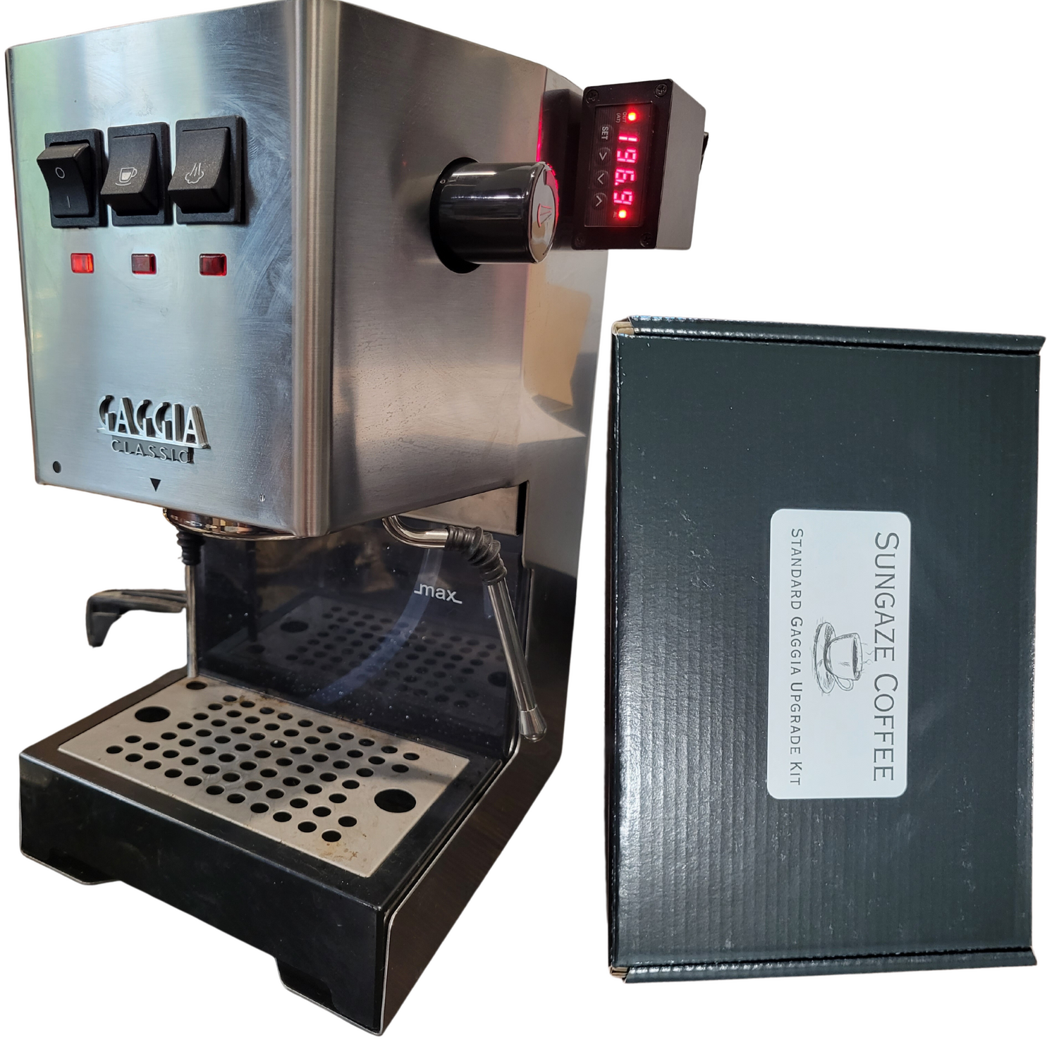
Parts Identification
Your kit should include the following:
Please Note: Your parts may look different from the images below
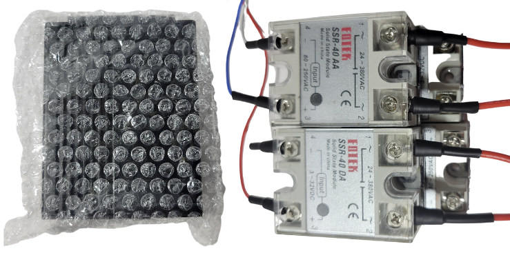
Main Components:
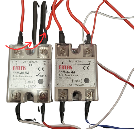
Wired Brew Relay, SSR-DA & Wired Steam Relay, SSR-AA
PID Controller + Enclosure
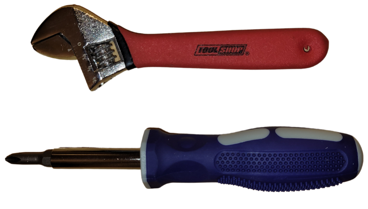
Tools:
Multi-Head Screwdriver (Yellow or Blue)
17mm Wrench or Adjustable Wrench
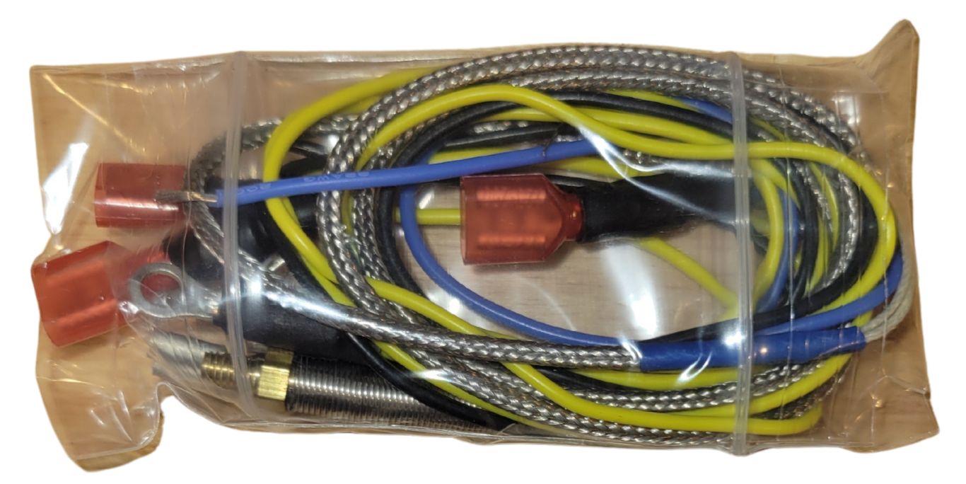
Wire Bundle Bag:
Yellow Female Spade to Ring Terminal Wire
Yellow and Black Piggyback Connector Wires
Threaded Thermocouple Sensor
Blue Jumper Wire
Blue Female to Female WireORPWM Wire Bag
(2 Male Spade Wires, & 2 Female Spade Wires)
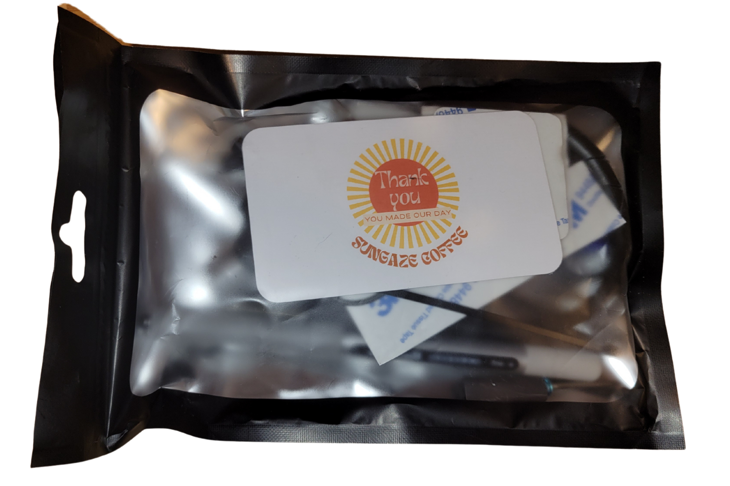
Parts Bag & Misc:
Alcohol Wipes x2
Spiral Wrap Cable Sleeve
Hex Key
Grommet x2
Zip Ties
Heat Shrink Cable Sleeves
Flow Control Knob (May be included inside your PID enclosure)
Thermal Compound
Uniball Pen
Mini Screwdriver
Large & Small Adhesive Pad
Wooden WDT Tool (Extras Kit Only)
Portafilter Keychain (Extras Kit Only)
58mm Portafilter Screen x2 (Extras Kit Only)
Backup Temperature Sensor (Extras Kit Only)
Before We Begin
Depending on your PID Enclosure type, your installation will be slightly different.
If you have the 3D printed enclosure, click the "Click Here" button below. If you have an aluminum enclosure, scroll below and continue reading this guide.
3D Printed Enclosure with Flow Control Knob
Aluminum Enclosure without Flow Control Knob
First Steps
(Aluminum Enclosure Guide)
Do not begin if your machine is still hot from recent use.
Remove the power cable from the back of your machine. Remove the portafilter, drip tray, solenoid blowoff tube (if present), and water tank.
Remove the water tank funnel cover. Take your Phillips(+) head screwdriver and remove the screws from the top of the machine, located in the funnel housing (highlighted below).
Pull upwards from the back and remove the funnel and top plate.
The picture above shows where the phillips (+) screws are that need to be removed.
WARNING: The wire colors on Gaggia Classic models made in different years and continents may not be the same. Please verify the wires on your machine by its connections before attempting your install.
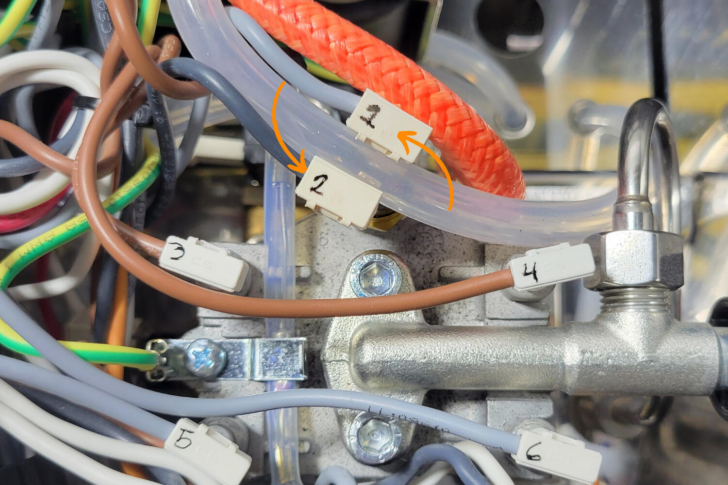
With the front of the machine facing you, take the pen included in your kit and number the connectors from 1 to 6 from left to right as shown below.
We will not be intentionally removing them during installation, but they may disconnect as we move the boiler. It is recommended to take a picture of your machine for reference.
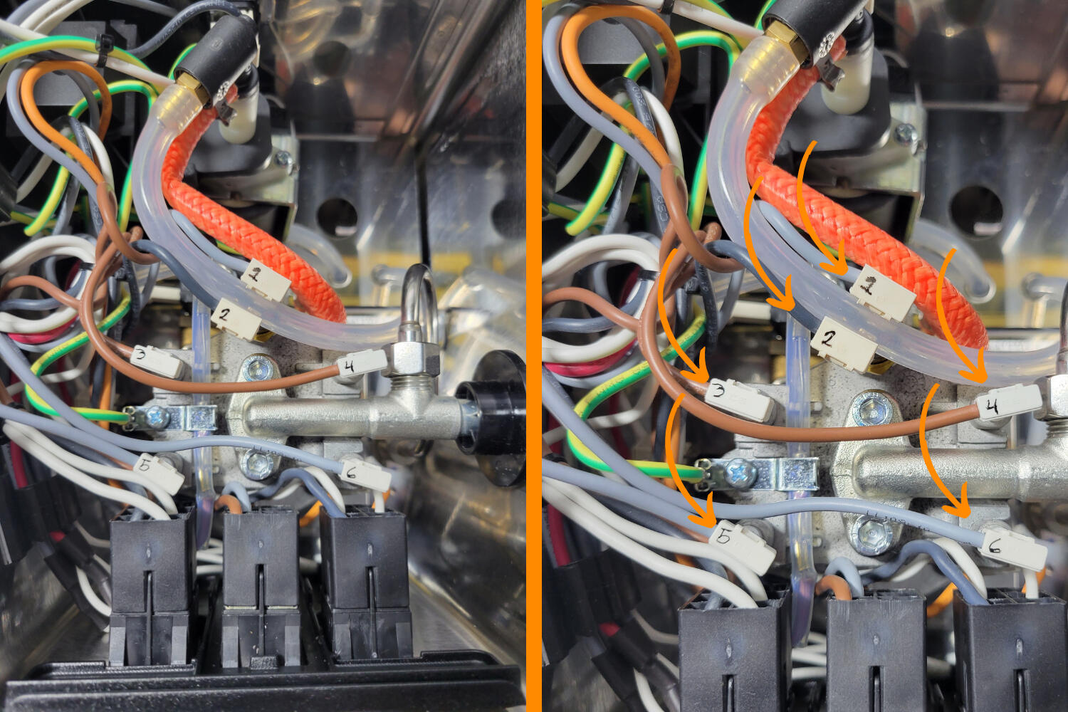
The picture above shows how you should number your connectors.
Remove the Steam Valve
You can skip to the next step if you are doing the flow control only upgrade.
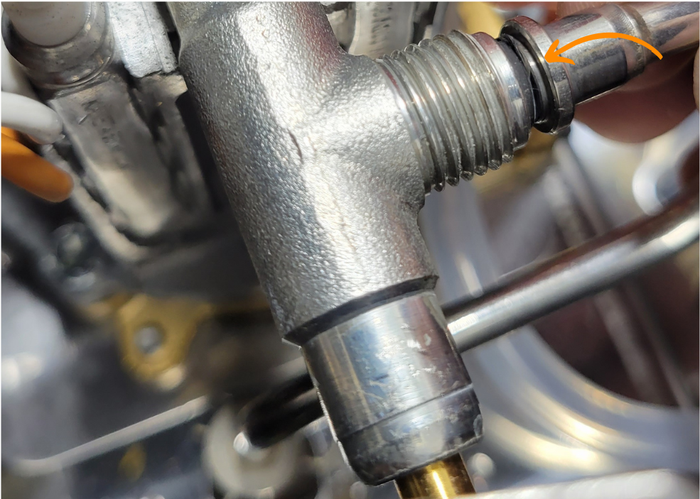
We need to detatch the steam wand. Take your provided pliers and loosen the nut that attaches the steam wand to the boiler.
When the nut is removed, pull the steam wand tube out. In older machines, the wand may be more firmly snug due to scale buildup.
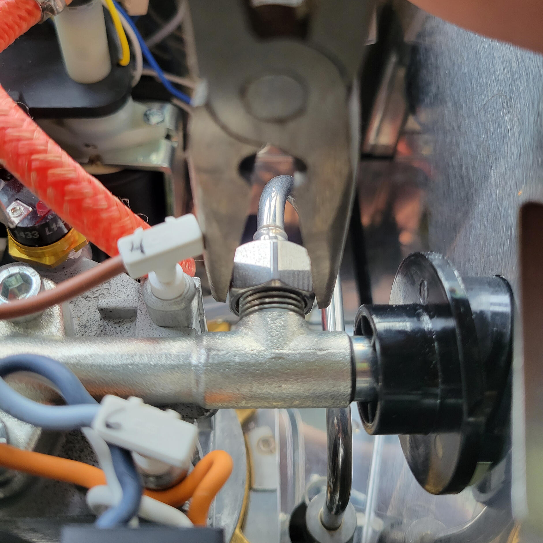
The picture above shows the nut to be loosened. The nut is right next to the #4 connector.
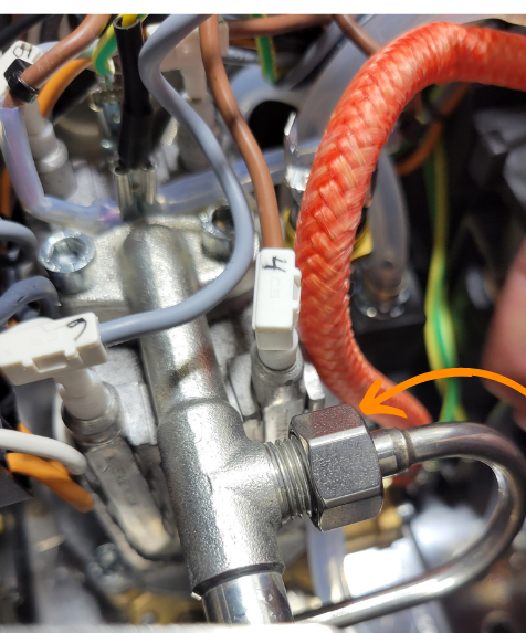
Loosen the nut and push the steam wand backwards to disconnect it from the boiler.
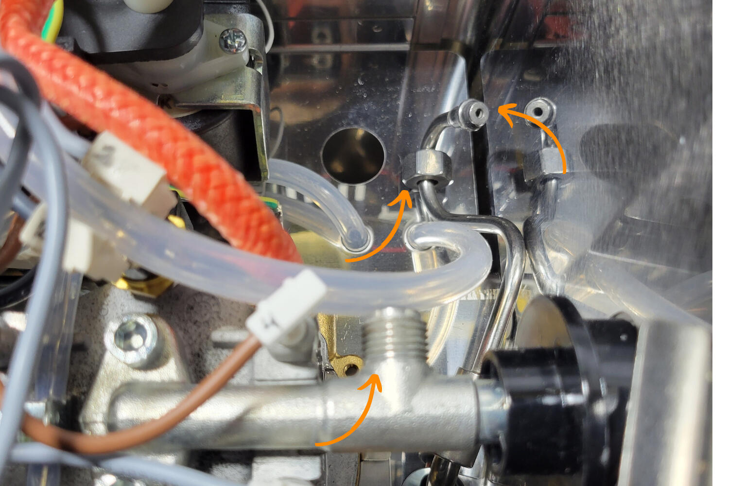
The picture above shows the disconnected steam valve that was pushed downwards and out of the way.
Loosening the Boiler
You can skip to the next step if you are doing the flow control only upgrade.
Next, the boiler will be unsecured from the machine housing. You will need the hex-head wrench (allen key).
The hex key has a hole in the middle. You will need to use the shaft of your included screwdriver to fully loosen and tighten the screws.
Looking up at the grouphead, there are four screws located next to the grouphead. Remove all four screws.
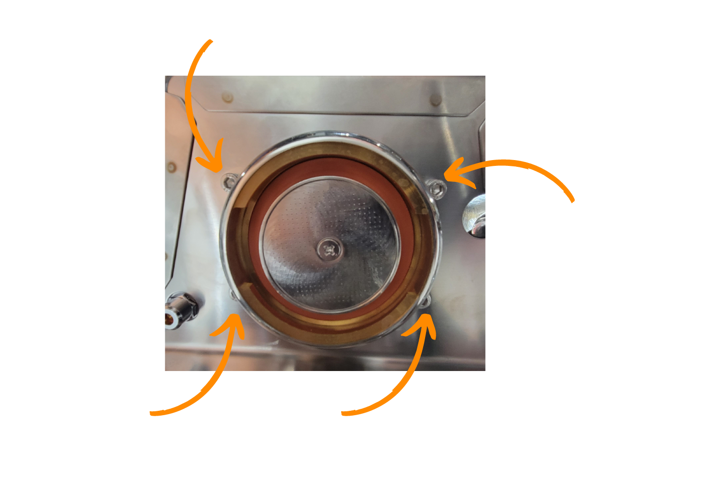
There are four bolts that hold the boiler in place, unscrew those until all four are removed. The four bolts are outside where you attach the portafilter.
Now that the boiler is loose, the steam knob can be removed.
To pull the steam knob off, grip firmly and pull away from the machine.
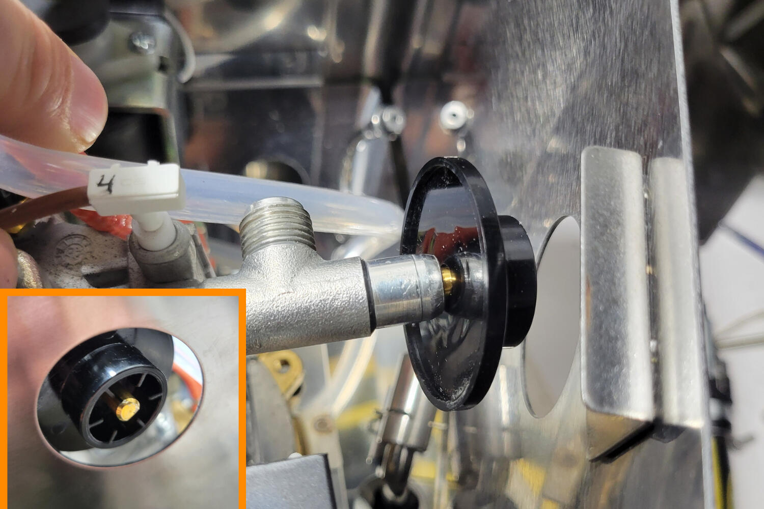
To remove the steam knob collar, pull the boiler up and away from the hole
Remove the Power Cable Entrance Fitting
If your machine has a power cable with only two prongs, you may skip this step. The power cable fitting does not need to be removed to maneuver in the machine.
For those with a three-prong power cable, take a picture of your power cable fitting from inside of the machine paying attention to which wires go where.
If you are in the USA, it's likely that your wires are colored as follows:
Green/yellow on the single side (ground), black on the top (neutral), and white on the bottom (hot).
Take a picture of the 3 wires so that you don't forget the order.
Disconnect these so that the three connectors are bare. You might have to use some force and wiggle them to get them to come loose.
Next, apply pressure to the top two tabs of the power cable entrance and push the top outwards slightly.
Then, apply pressure to the bottom two tabs and push outwards.
If you did this correctly, the power cable entrance should now be free.
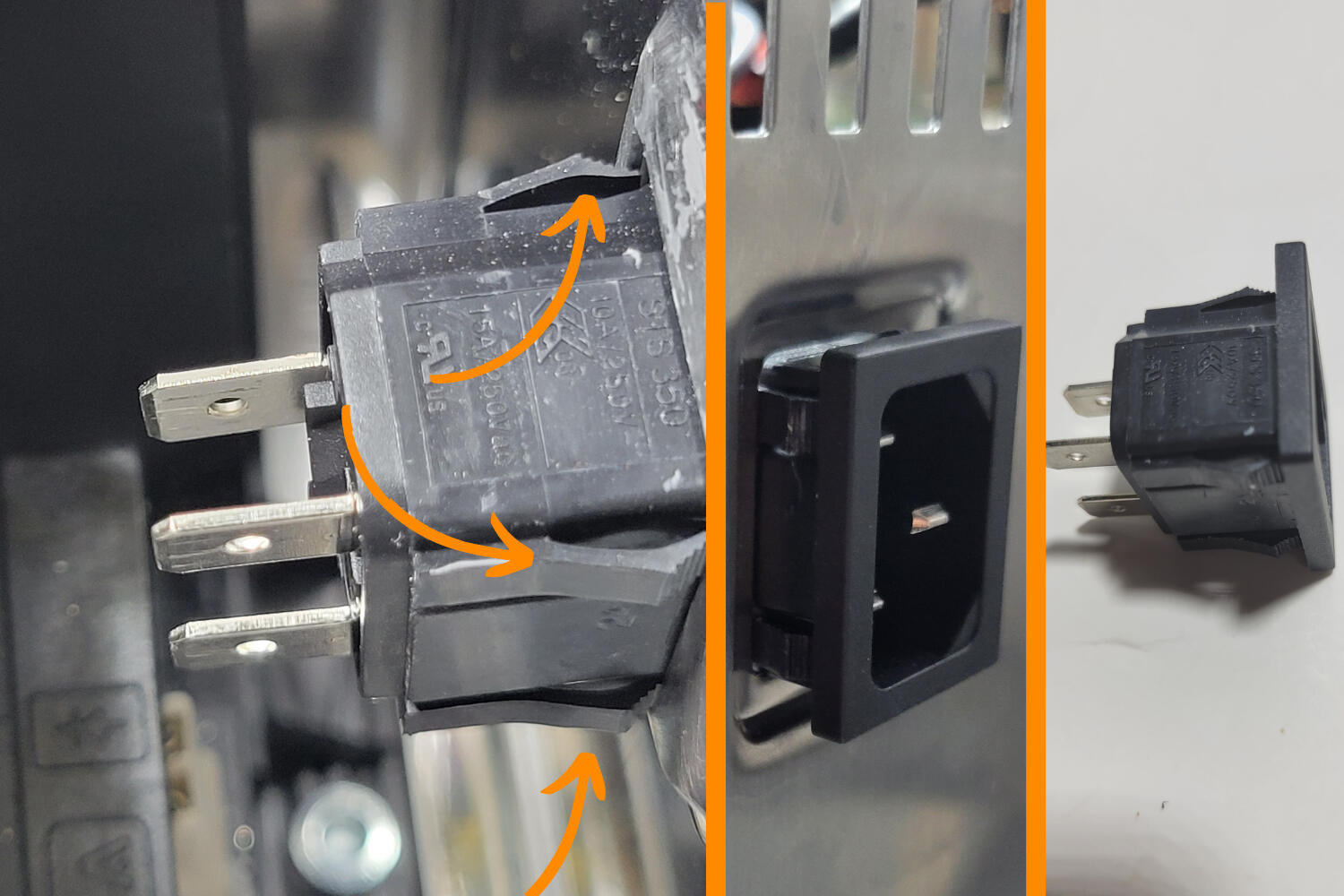
The picture above on the left shows the 4 tabs to depress to remove the power cable entrance holder. The next picture shows the entrance slightly removed, and the last picture is the entrance fully removed from the machine.
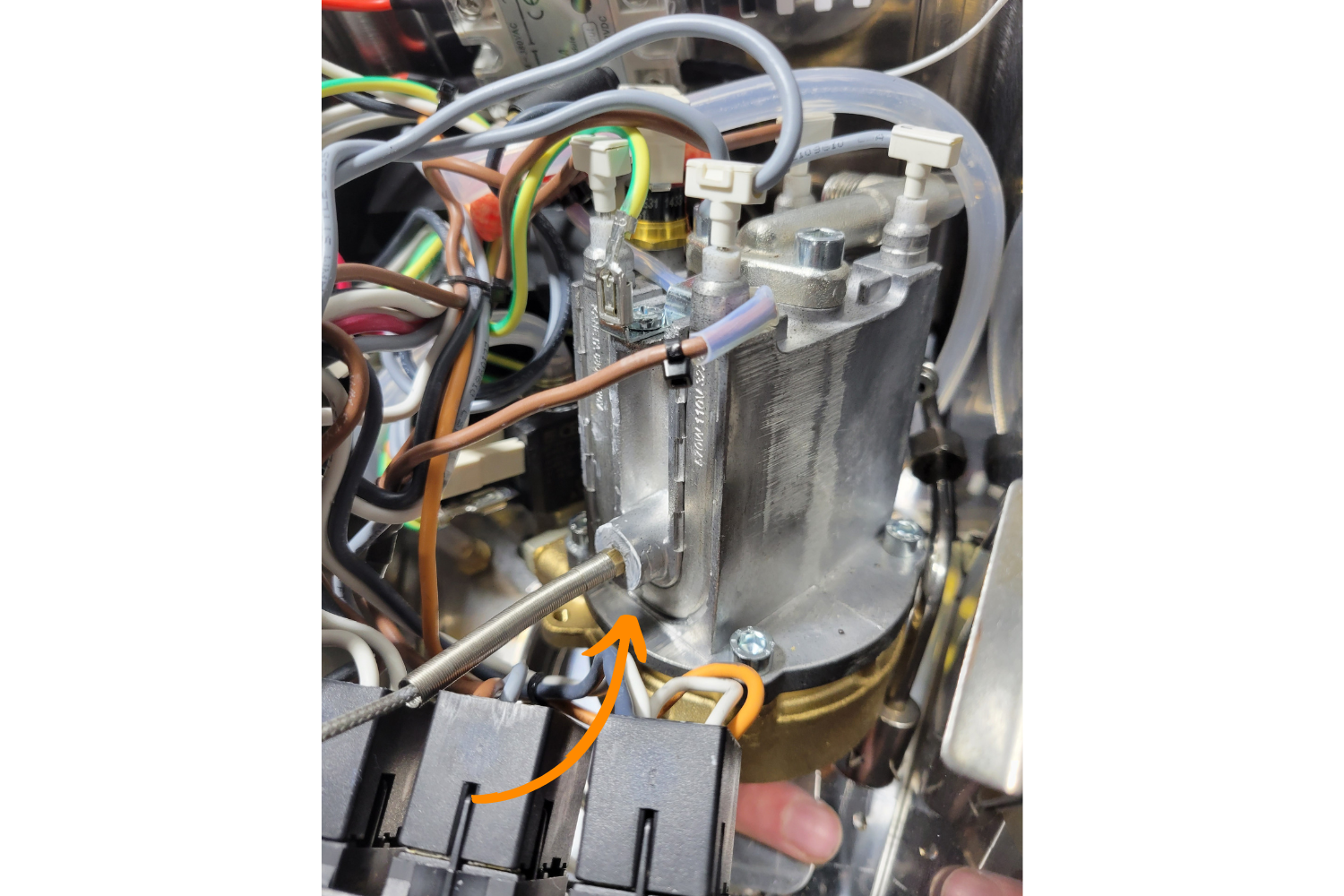
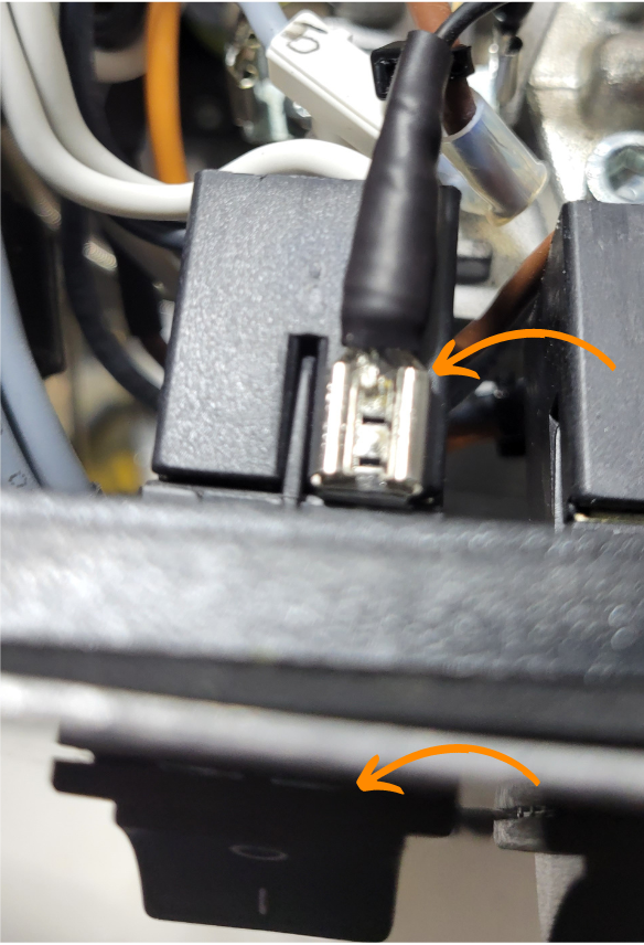
Disconnect the Brew Pump Connector
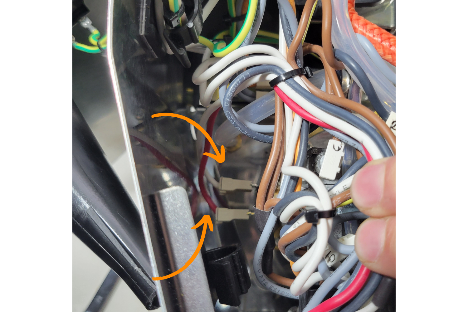
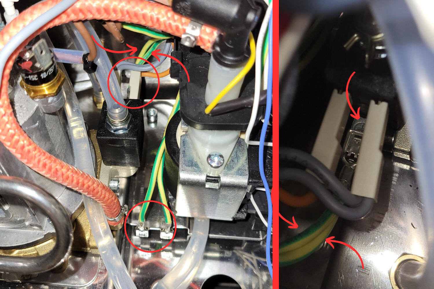
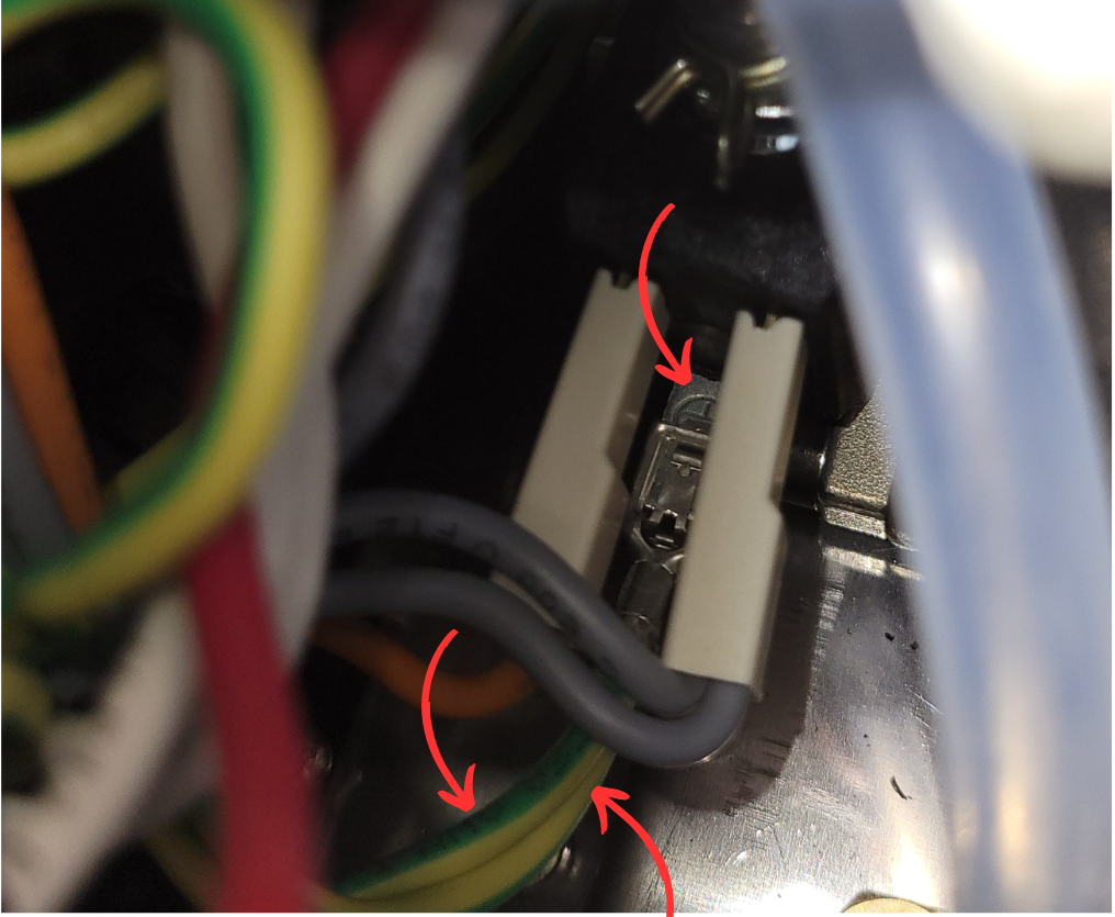
There are two wires connected to the brew pump, a thinner cable and a thicker gray cable. Disconnect the thicker wire. You may need to push against the pump to get your hand into position..
I like to use the thicker flat heat to press against the connector of the thicker wire on the water pump. Trying to fit your hand may be difficult.
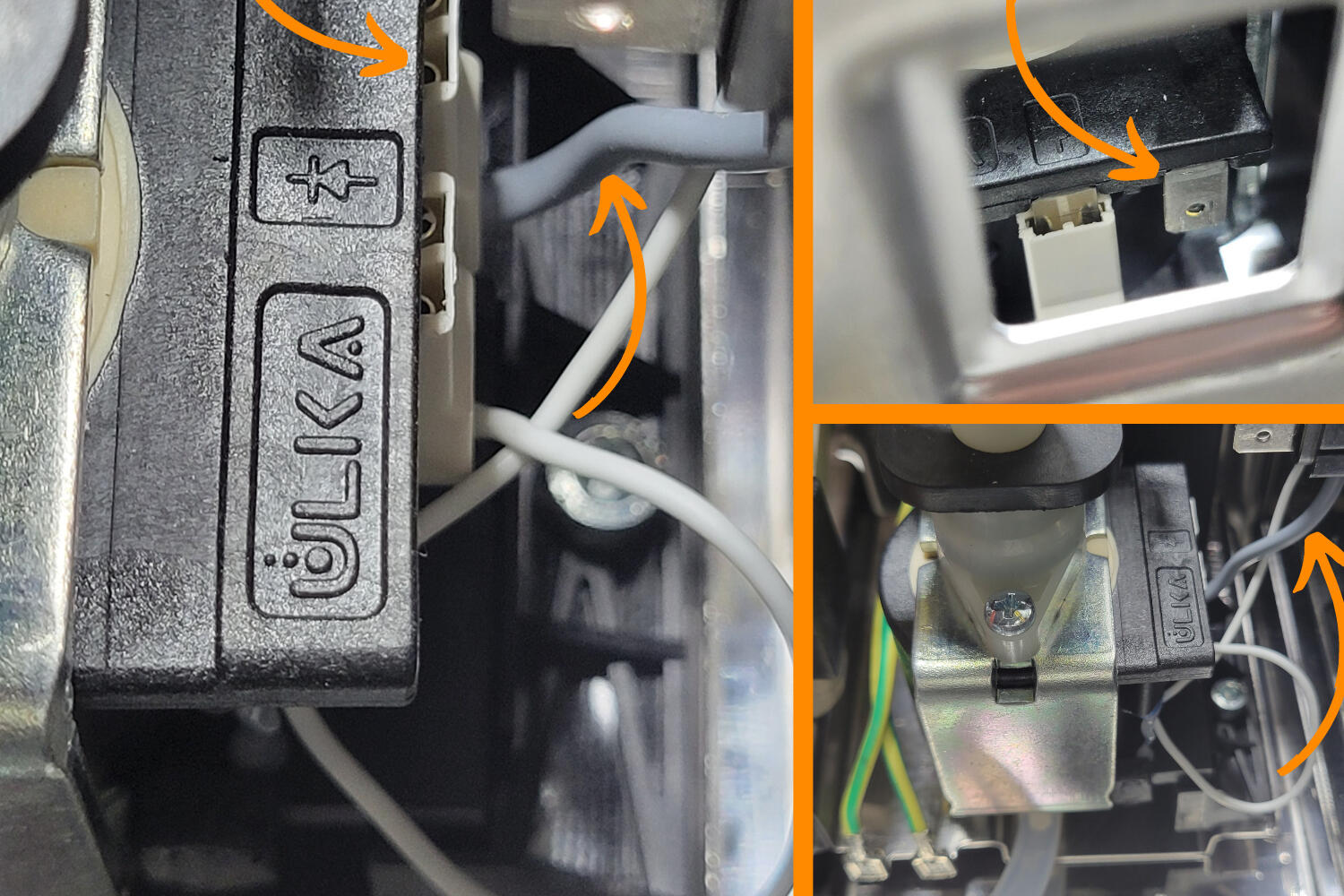
The picture on the left shows a close up of the brew pump and has two arrows pointing to the wire to unplug. The bottom right image shows a zoomed out angle of the brew pump. The top right image shows what the connector will look like once disconnected.
If you don't think you can fit your hand / screwdriver behind the pump to disconnect the thicker wire, click the button below to see how to disconnect your power cable entrance to free up some space.
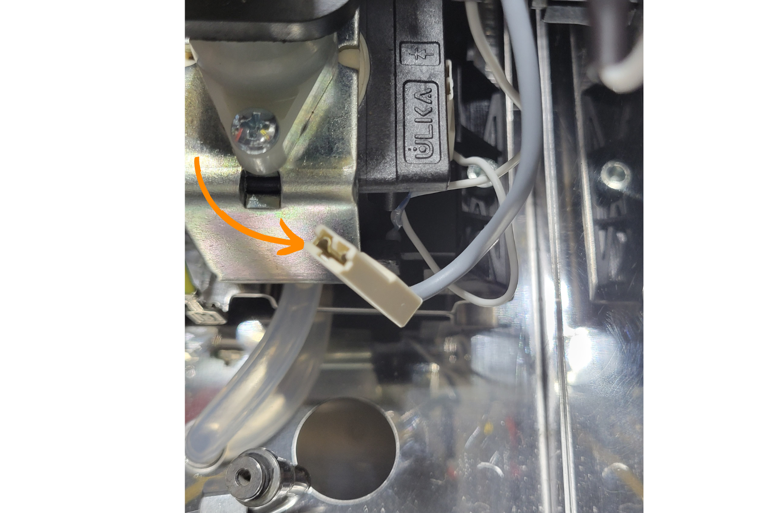
The image above shows the gray wire disconnected from the brew pump and out of the way.
Connect the Water Flow Control Switch
Attach the shorter, blue female wire to the tab on the pump where the wire was removed in the previous step. You may need to slightly push the pump aside to attach the wire.
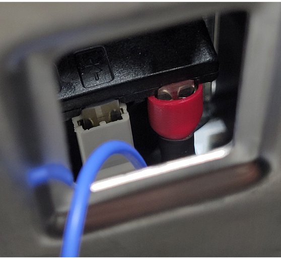
The picture above shows the shorter female blue wire connected to where the gray wire used to be on the water pump.
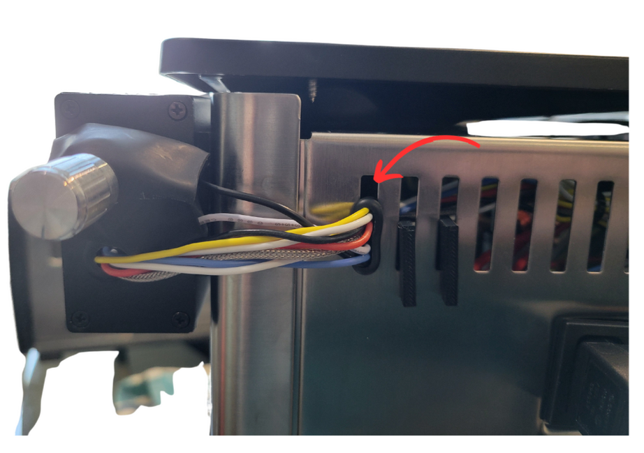
Next, we will push the two wires from the dimmer knob through the back vent slot that is furthest to the left. Before you insert the wires into your machine, put your grommet over both of your dimmer knob wires. This will help with installing the grommet into the vent later.
Sometimes it's difficult to insert the grommet into the vent, if that is the case use your flathead screwdriver head to force the grommet into the vent hole.
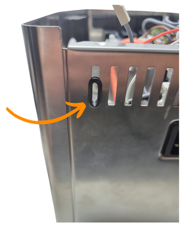
The picture above shows the grommet installed into the correct vent slot. NOTE: the wires are missing, you will not insert your grommet like this. This is simply for reference.
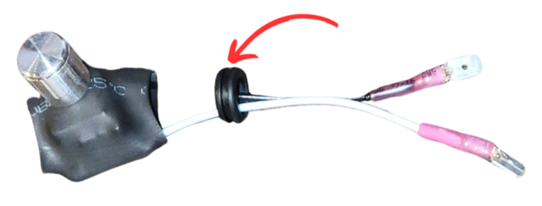
Next, take the dimmer switch and push both male ends through the newly installed grommet. Your switch should hang out of the back of your Gaggia like the image below.
Your grommet does not need to be fully inserted into the vent slot yet. It's easier to wait until the rest of the wires are passed through the vent
The picture above shows the dimmer switch wires pressed through the grommet and the picture on the right shows both male ends pushed through the grommet into the machine.
The dimmer switch wires will connect to the blue wire from the previous step and the gray wire that used to attach to the pump.
Take the black male wire from the dimmer switch and attach it to the gray female wire.
Take the white wire with the male end and connect it to the blue wire.
The picture above shows the wires fully connected for the dial switch.
This concludes the electrical portion of the dimmer switch installation. Use a zip tie, included, to clean up any loose blue wire if you so choose.
The picture above shows the wires zip tied out of the way.
These steps below are for those doing the flow control-only upgrade.
Take your alcohol wipe, wipe down where you'd like your dimmer knob and take your adhesive and stick the dimmer knob whereever you'd like.
You may now reinsert your power cable entrance fitting. After installed, reconnect the cables exactly how they were before they were removed.
Lastly, take your lid and reattach it to your machine. Use your screwdriver to secure the top two screws. Make sure the water funnel is in place, if the water funnel doesn't match up with the water hole, your lid won't sit correctly.
If you watch this video, it will explain how preinfusion works with your dimmer knob.
Congrats on your flow control upgrade!
Remove the Brew Thermostat
There are two thermostats on the boiler. The thermostat on the top of the boiler controls the steam temperature; the thermostat mounted to the side of the boiler controls the brew temperature. The brew thermostat, mounted to the side, will be replaced with a thermocouple read by the PID controller.
Pliers and a flathead screwdriver are needed to remove the brew thermostat, located on the side of the boiler.
First, lift the boiler and grouphead up and out of the hole and rest it inside the machine, towards the right when facing the front of the machine. Be careful not to bend anything too far in either direction.
Your boiler will look like this once you move it out of the way to make room for the brew thermostat removal.
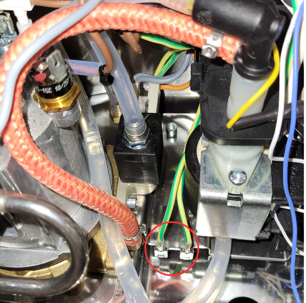
Some wires may need to be moved to access the brew thermostat. With the flathead screwdriver, carefully remove the two leads from the brew thermostat.
Your boiler will look like this once you move it out of the way to make room for the brew thermostat removal.
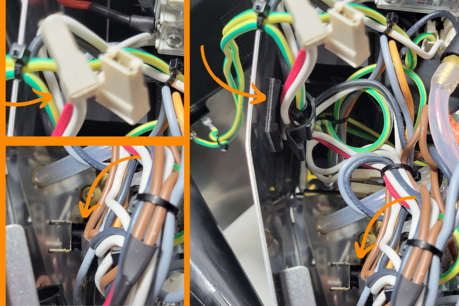
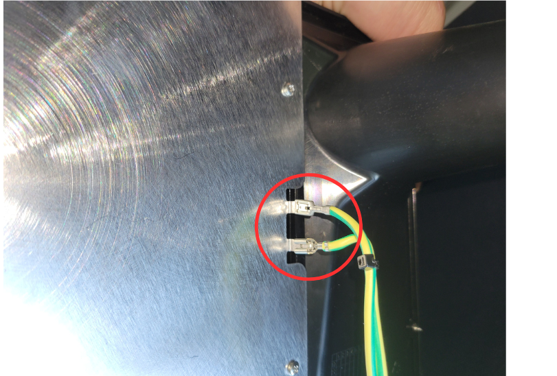
After the two connectors are disconnected, take them and pull them upwards and put them out of the way in the clip with the green and yellow wires, as shown in the image above (if your machine does not have a ground, there will be no clip or green wires).
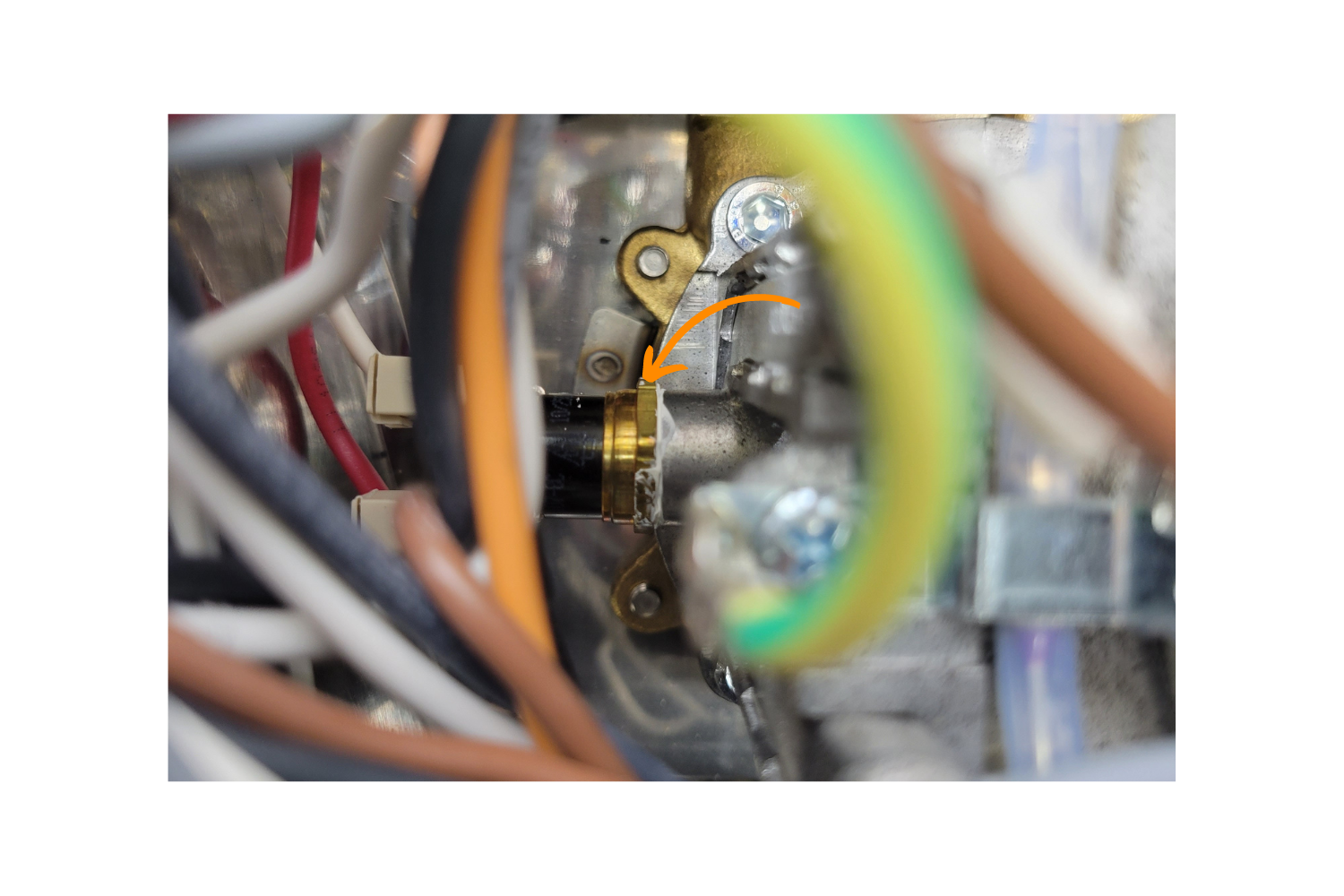
Carefully unscrew the thermostat, first with pliers, and then by hand if possible.
Remove the brew thermostat, it is no longer needed.
Install the New Brew Sensor
Apply a very small dab of thermal compound to the threading of the RTD temperature sensor like the image below. Then, take one of your heat shrink sleeves and place it over the top of the threads and use it to push the thermal paste into the threads. When you are done, there should be little thermal paste left on the temperature sensor, with the majority of it inside the threads.
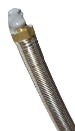
Do not overapply the thermal compound, your machine should have some thermal compound still intact from the OEM thermostat. If you apply a glob of thermal compound like the picture above, you will need to wipe excess off so that it is only on the threads.
If you use too much thermal compound, your sensor may have trouble reading an accurate temperature and your temperature will jump around. The picture below is the absolute maximum thermal compound you should use, we reccomend using less than the picture above or none at all.
The sensor will be threaded into the boiler where the thermostat was removed. Due to the metal sheath on the temperature sensor, it may be difficult to rotate it into the existing brew thermostat threads.
It is critical that you are careful with the temperature sensor as it is delicate. You will want to make sure you are not twisting the inner wires while threading it into place.
Start the threads by hand, between a ¼ to ½ turn. Once it has begun threading, carefully continue to thread it by turning and rotating the the braided cable of the RTD sensor in a circular motion until it is close to snug.
Be careful to allow the cable to untwist itself, if necessary (without unthreading it). Then finish threading by hand.
The picture above shows the temperature sensor fully screwed and hand tightened into the boiler.
Put the boiler and grouphead assembly back through the hole to its original position.
Adding your Neutral Wire Tap
The wiring to power the PID temperature controller depends on the model.
To continue, click your model below.
Adding your Neutral Wire Tap (Evo)
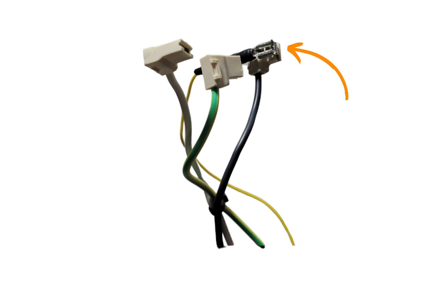
The on/off rocker switch should have four wires connected to it, two on the top and two on the bottom. Take a picture for reference.
In order to power the PID, a piggyback spade connector is needed. However, due to how the switch is wired, it is not physically possible to piggyback off of the correct wire- the toggled side neutral wire.
The top wires and the bottom wires on the switch must be reversed so that the correct wire can be accessed. This will not change the behaviour of the switch; it will merely allow the PID to also be turned on and off by the switch instead of always being on.
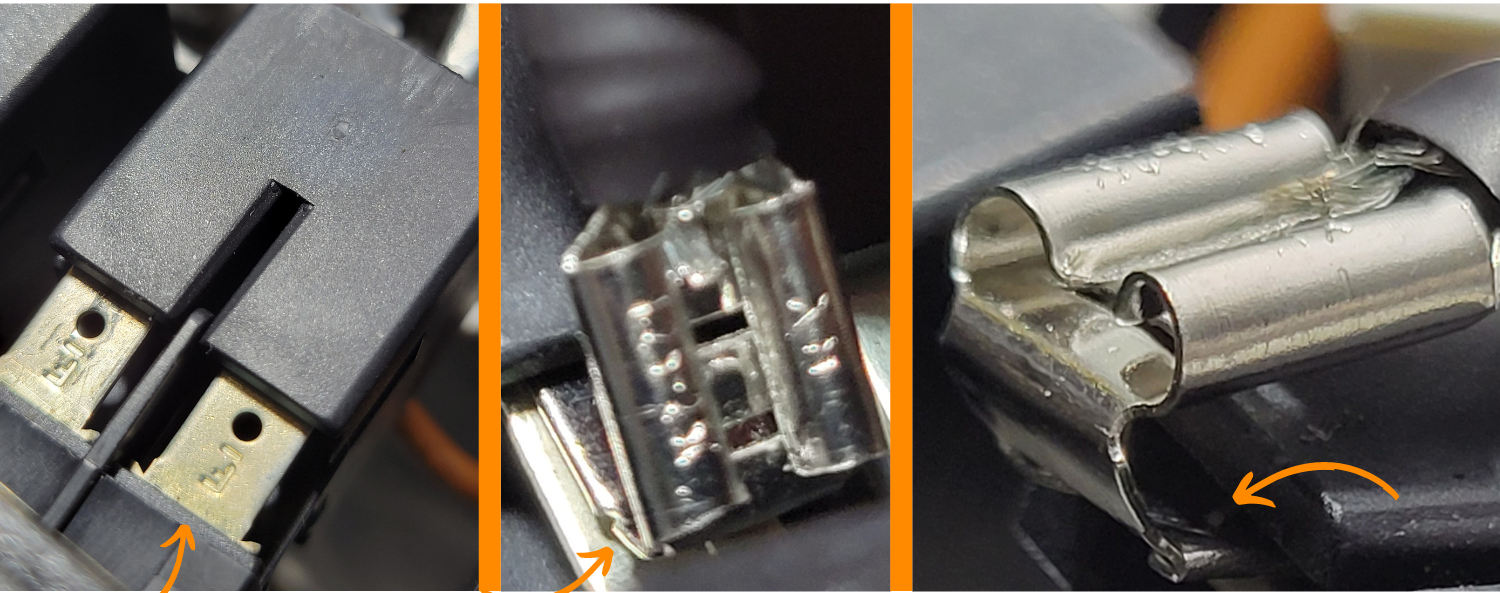
First, remove the block connector from the switch. Next, all four connectors must be disconnected.
Insert the flat head screwdriver (thick side) into the block connector. You'll want to come straight on from the top. After applying some pressure, the female end inside the block connector housing should start to move backwards, you should now be able to pull the wires back and out of the connector.
The picture above shows where the flat head of the screwdriver needs to be inserted to push the wire out.
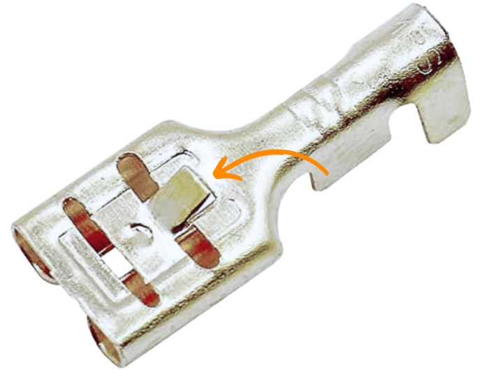
The female end of the wires have a tab that locks them in, which was depressed to remove them. Push the tab back up to about 30° with the flathead screwdriver.
Repeat this step with the other three connectors. When reconnecting the wires, swap the top left with the bottom left and the top right with the bottom right- reference your photo to verify this was done correctly. When the connectors are pushed back in, there should be an audible click if the tab was reset properly.
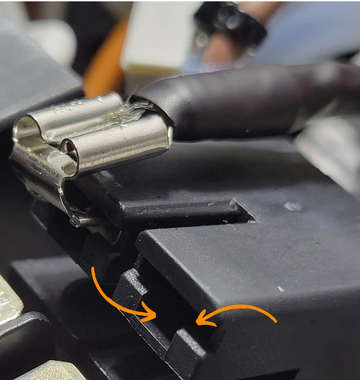
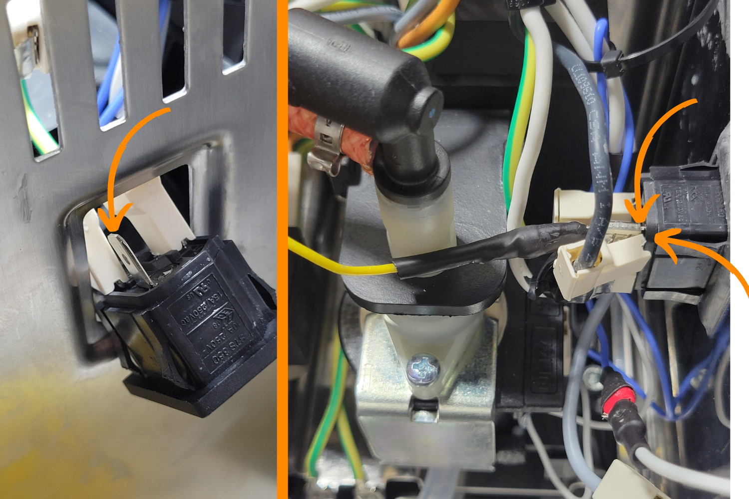
The picture above shows how your piggy back connector should sit on the Gaggia on/off rocker connector.Secure the other end of the black cable to the side with your other wires.
Left- the switch connections without the piggyback spade connector. Center- the placement of the piggyback spade connector. Right- the connector deeply inserted into the gap between the block connector and the on/off rocker switch.
Take the black wire with a piggyback connector and slide a heat shrink cable sleeve over the exposed part of the connector andhook the piggyback connector end between the top right block connector (when facing from the front of the machine) and the on/off rocker switch, and push the block connector fully into place.
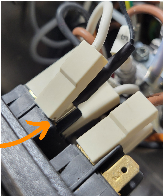
Adding your Neutral Wire Tap (Pro)
In order to power the PID, a piggyback spade connector is needed. However, due to how the switch is wired, it is not physically practical to piggyback off of the correct wire- the toggled side neutral wire.
Therefore, the top wires and the bottom wires on the switch must be reversed so that the correct wire can be accessed. This will not change the behavior of the switch; it will merely allow the PID to also be turned on and off by the switch instead of always being on.
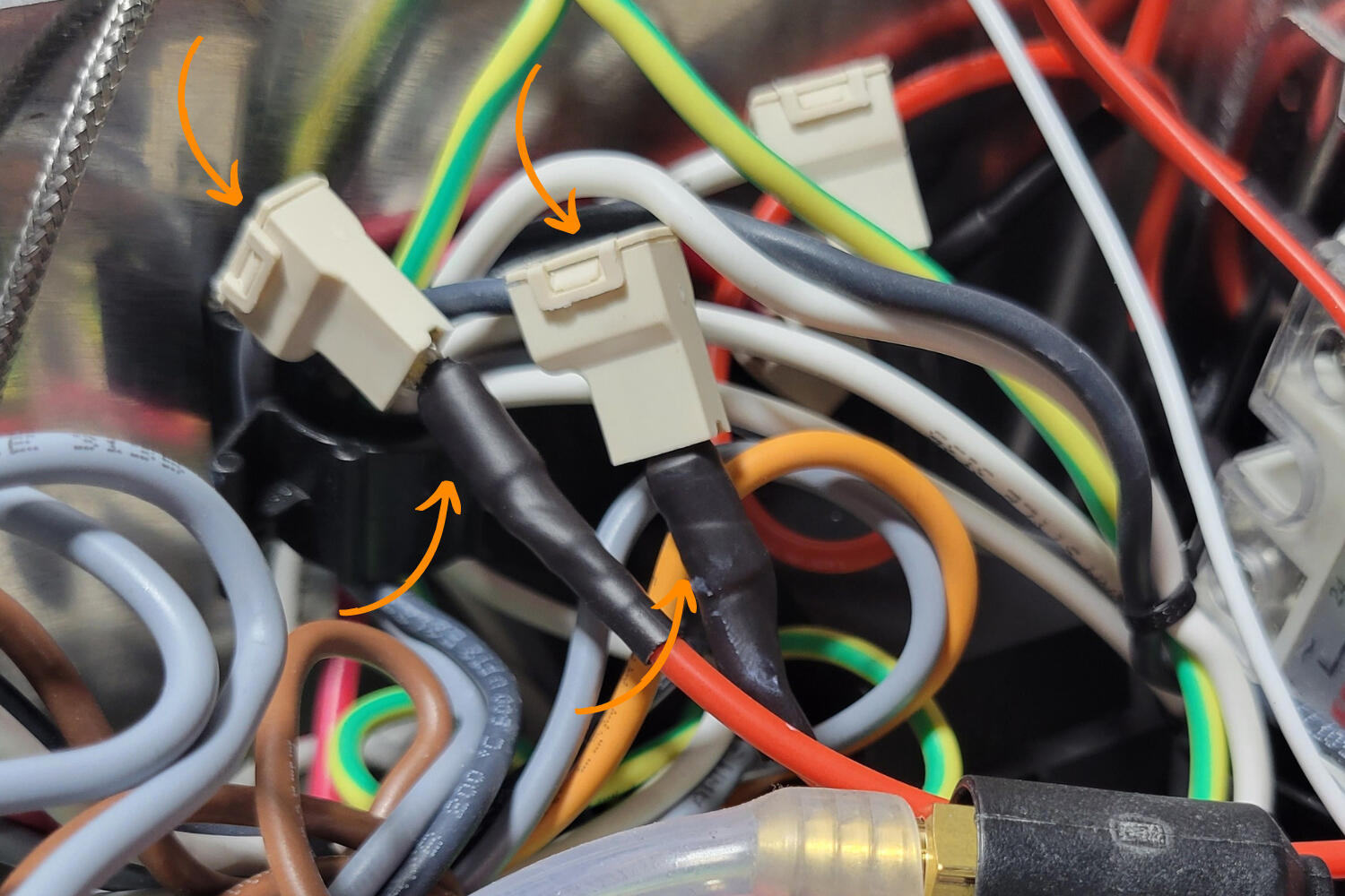
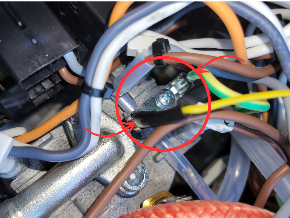
Take a photograph of the switch to document the location of the four wires. Carefully swap the position of the wires, swapping top right and bottom right; top left and bottom left. The spade connectors should pull off.
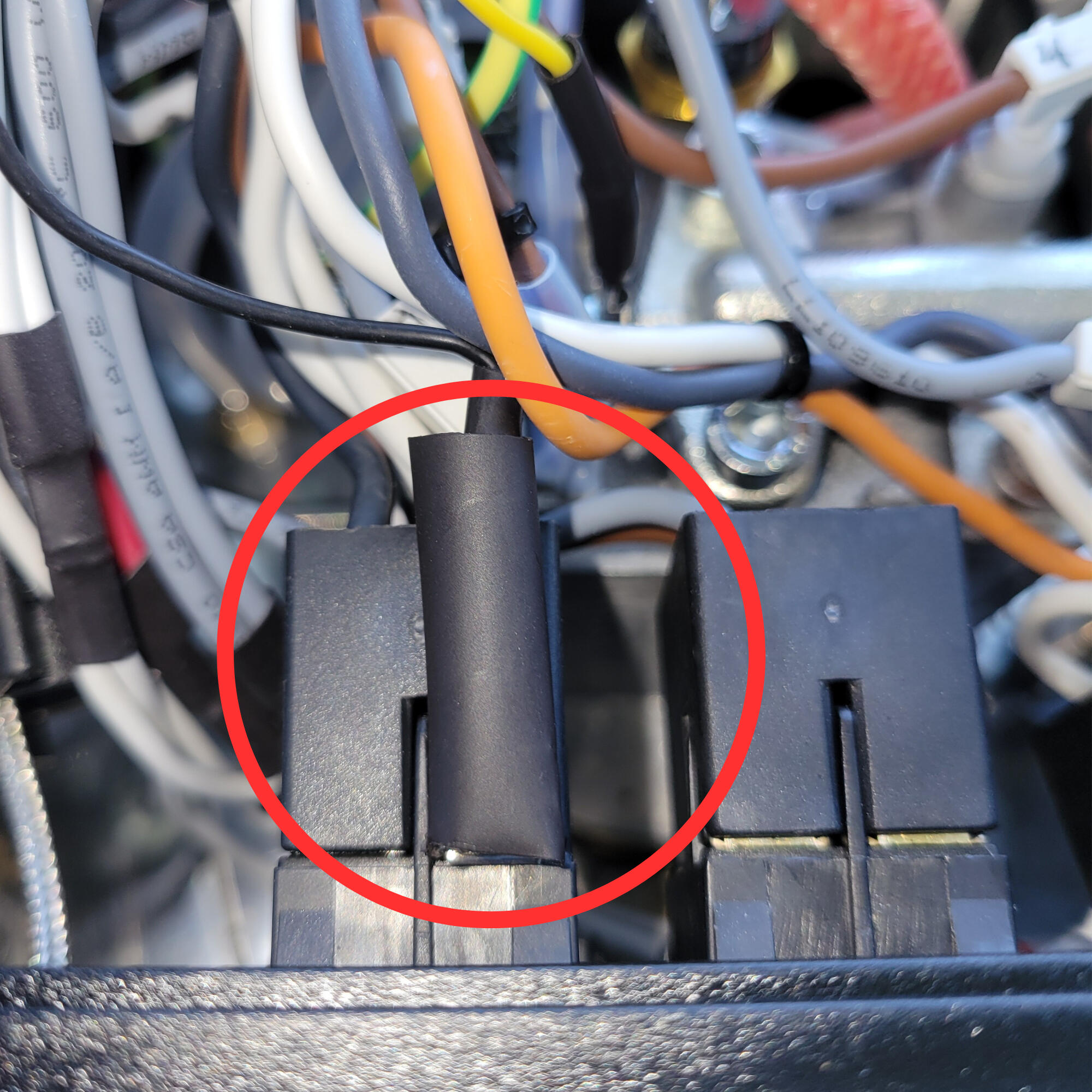
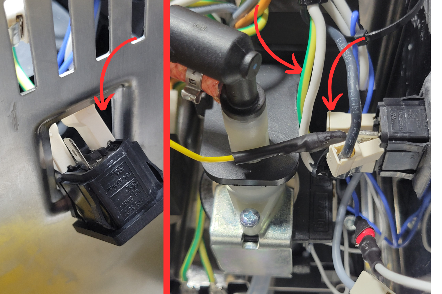
In the image below, the two white wires on the right were swapped and the black and brown cables on the left.
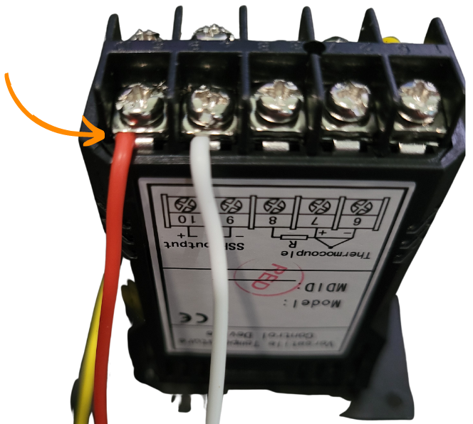
The arrow is pointing to the wire that needs to be tapped. Remember, this is AFTER we swapped the top and bottom cables on both sides.
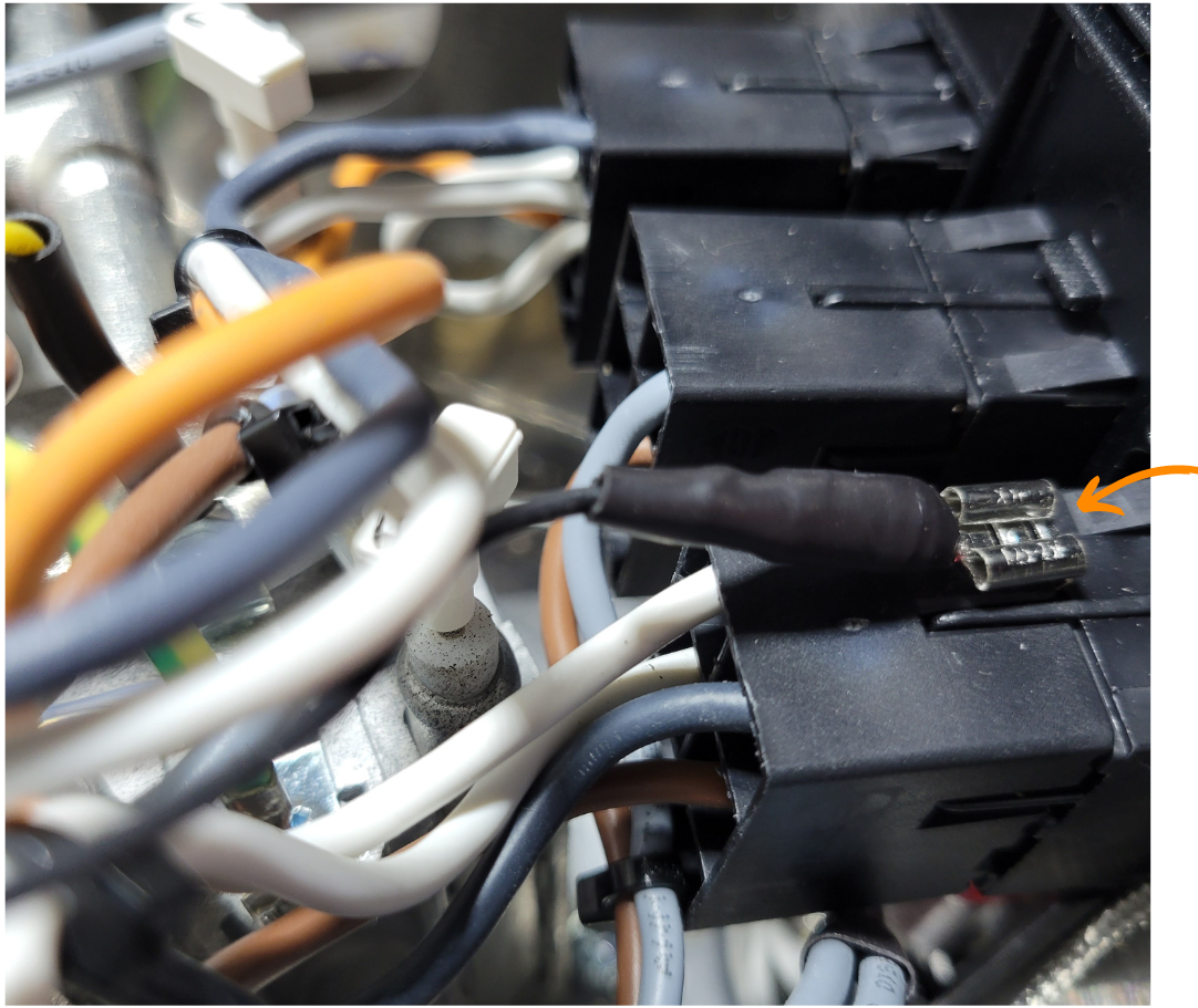
Next, disconnect the top right connector (as seen from the front, formerly the bottom right connector, as seen in the image).
Insert the male end of the black wire with the piggyback connector into the female end of the wire just removed.
Plug the female end of the piggyback connector into the top left connector of the on/off rocker switch. The wire configuration should match the image below.
The arrow is pointing to the wire that has been tapped. The factory connector will sit above the newly added piggyback wire.
Adding your Ground Wire
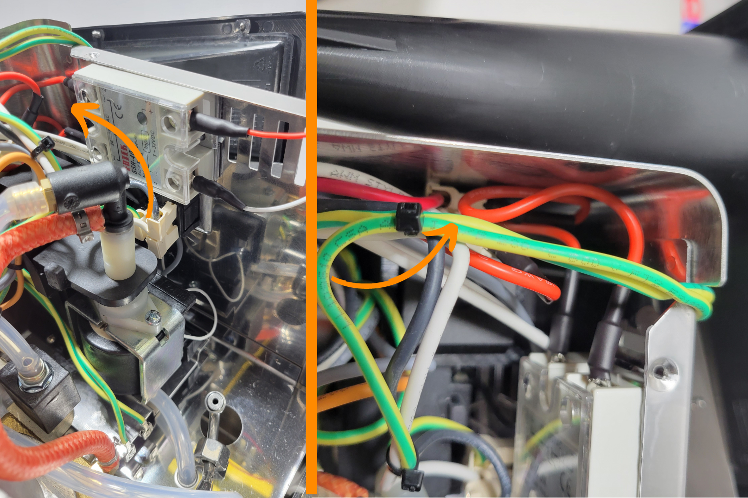
The boiler has two grounding posts right next to each other, located next to the thermal fuse on top of the boiler. If your machine is a model with a ground (three prong power), there will already be a green and yellow wire attached to one post.
Take the yellow wire with a female connector on one end and the ring connector on the other and attach the female end to an unused ground post on top of the boiler. Feed the end with the ring connector through the grommet in the back of the machine..
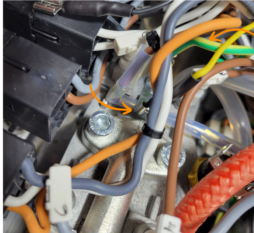
Both grounding post locations on top of the boiler. One arrow points to the newly installed yellow arrow and the other points to the factory installed green/yellow cable (if present).
Connect the Hot Wire Tap
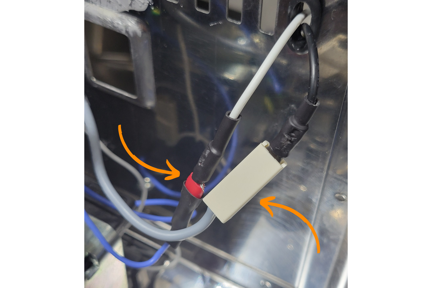
Take the yellow wire with the piggyback spade connector and connect the male piggyback end to the female end of black wire removed from the power cable entrance connector, located in the back of the machine. This should be the hot wire, see the image below.
The picture above shows the yellow piggy back connector wire attached to the black power cable entrance wire.
If you had to remove your power cable entrance to tap the water pump, lightly press the power connector back into the housing without engaging the tabs. Using your photograph, reinsert the wires in their former positions. Once they are connected, push the connector back into the housing.
Left- the top pin on the connector housing, where the yellow connector with piggybacked black wire should connect. Right-the yellow wire connected to the machine with the power cable entrance fully reinserted.
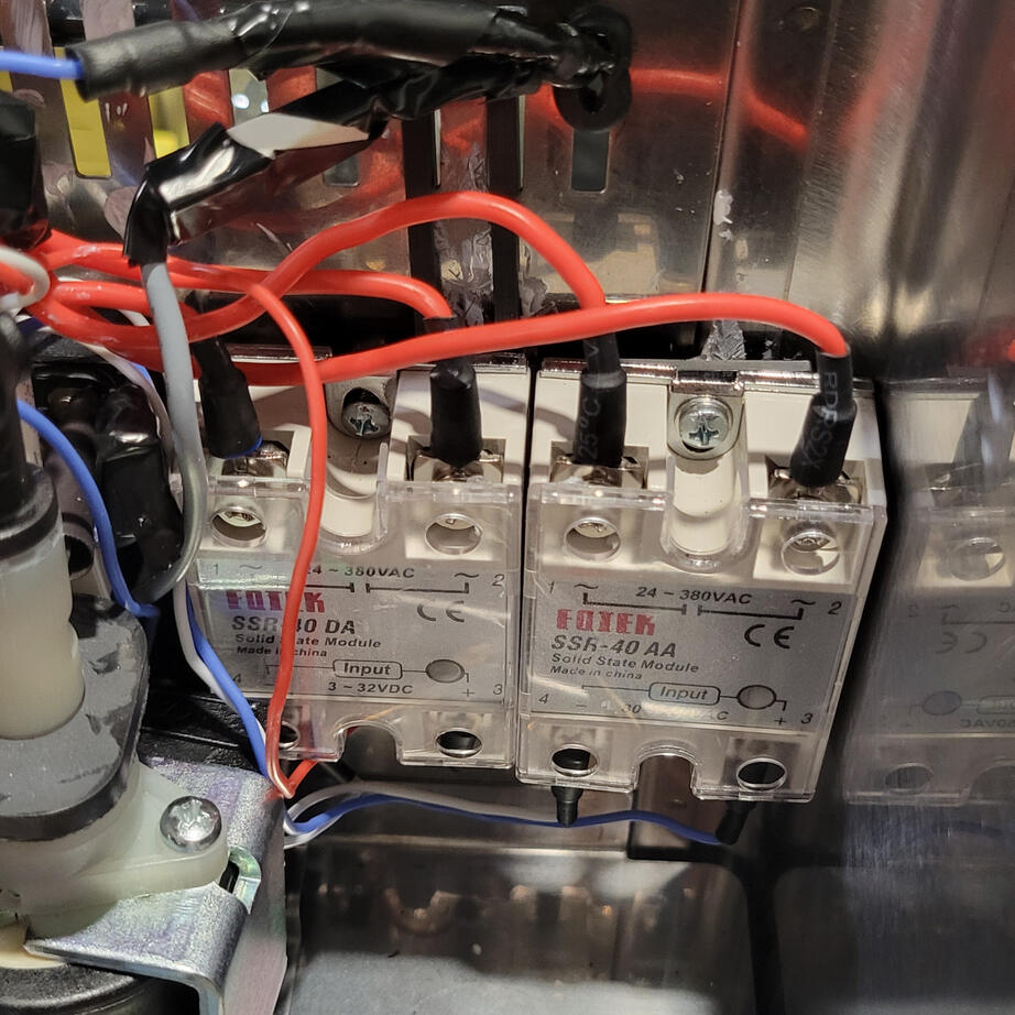
Install & Mount both Relays
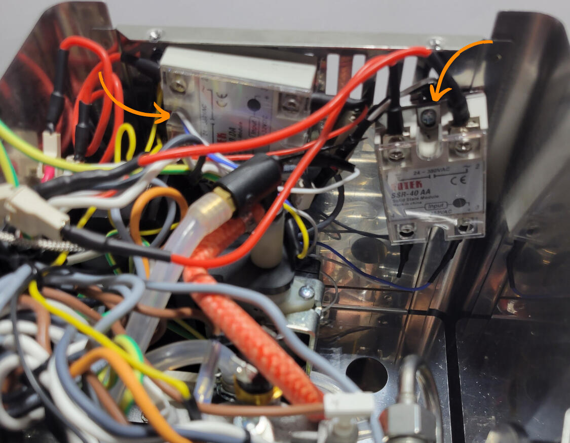
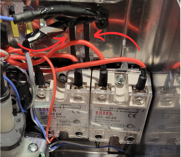
The final installation. Notice that the steam relay is mounted to the farthest hole to the right. The brew relay is mounted on the second farthest to the left vent hole. The screw is going through the red/red side of both relays.
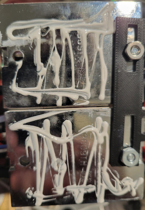
Start with the Brew Relay, the SSR-DA, the one with the red and white wires. Apply thermal compound to the back of the relay-9-12 dots and should have good coverage.
Take the screw, washer, nut, and mini screwdriver from the parts kit. Unscrew the nut and take it and the washer off.
Using the mini screwdriver, thread a screw through the hole in the relay on the red red side..
Using the screwdriver to hold the screw in place, push the screw through the second from the leftmost vent hole (when viewed from the front of the machine). Mount the relay horizontally, with the red red side on the left and the red/white side on the right (when viewed from the front of the machine). Thread and tighten the nut onto the screw.
The relay should slightly extend past the power cable entrance.The leftmost vent hole should be visible.
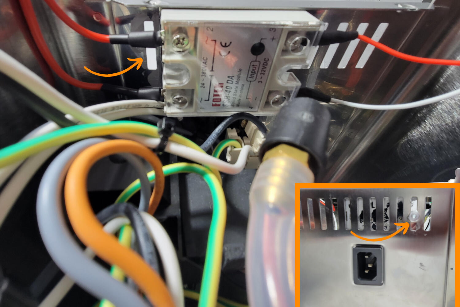
Left- the correct placement of the Brew Relay. Right- location of the screw and nut.
Next, take the Steam Relay, the SSR-AA, the one with blue and white wires.
Apply thermal compound to the back of the relay, again between 9-12 dots.
Using the mini screwdriver, thread the screw through the red white side of the relay. Push the screw through the vent hole with the rubber grommet, below the grommet.
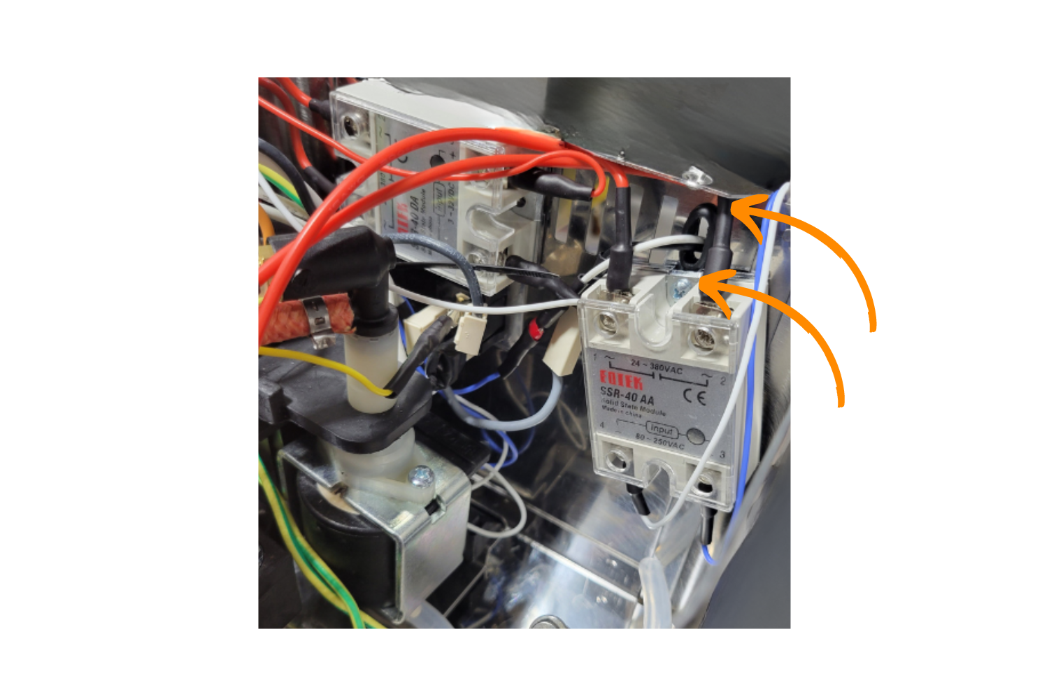
The correct placement of the Steam Relay. Note that the screw is placed in the same vent hole as the rubber grommet, below the grommet.
Lightly thread the nut so that the relay will not fall out, then angle the Steam Relay slightly to the right (as viewed from the front of the machine)t.
The Steam Relay (SSR-AA) angled to the right as much as possible.
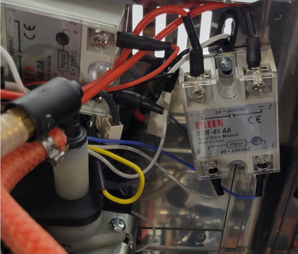
Connect the Relay Wires
Plug the two thick red cable male ends on the Brew Relay, (SSR-DA), to the two connectors removed from the brew thermostat. It does not matter which orientation they are connected.
Both wires that were formerly plugged into the brew thermostat connected to the brew relay (SSR-DA).
Use a ziptie to tidy up slack from the Brew Relay.
The picture above shows the freshly connected wires, tucked out of the way.
Skip to the next step if you're not installing the steam upgrade.
If you're installing the steam upgrade, continue below.
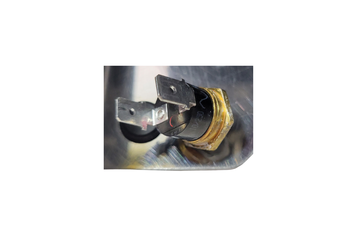
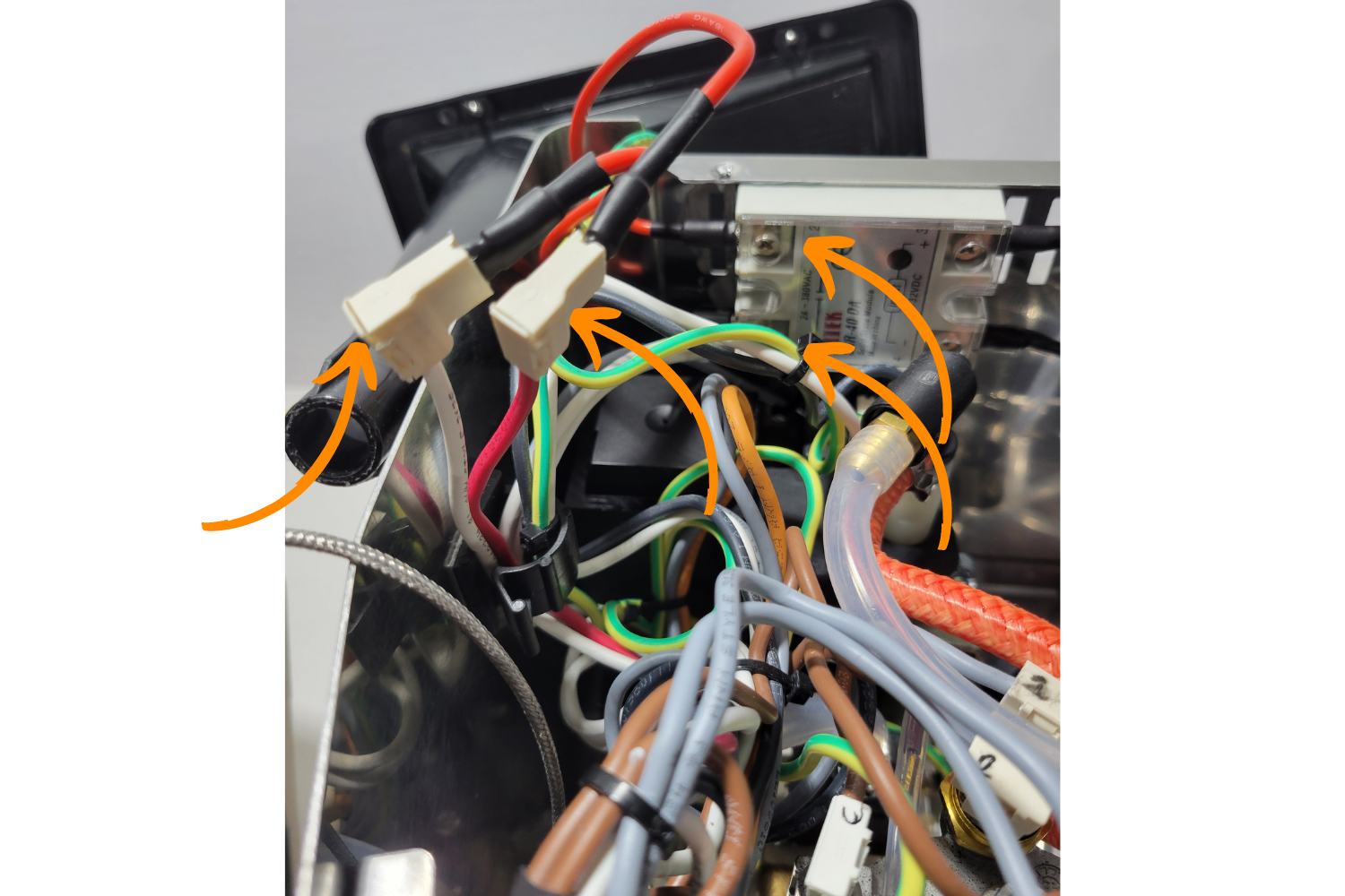
Remove the #1 and #2 steam thermostat connector wires.
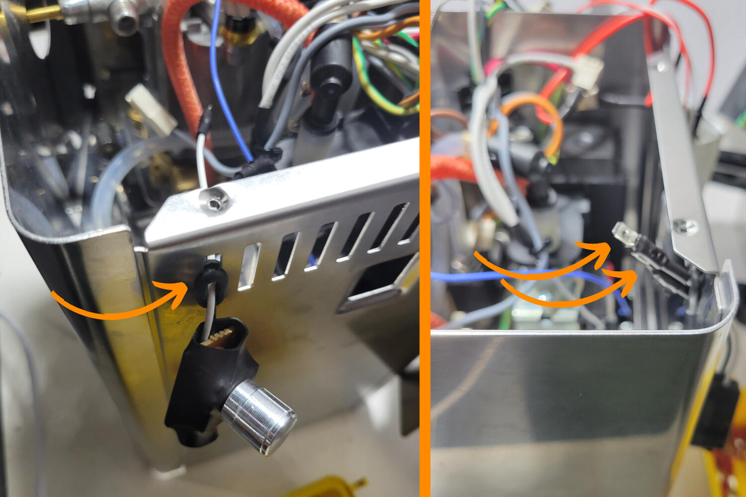
The two numbered connectors on the steam thermostat that need to be removed.
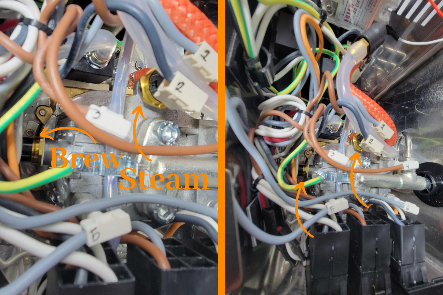
Connect the #1 and #2 steam thermostat connectors to the #1 and #2 male spade connectors on your steam relay.
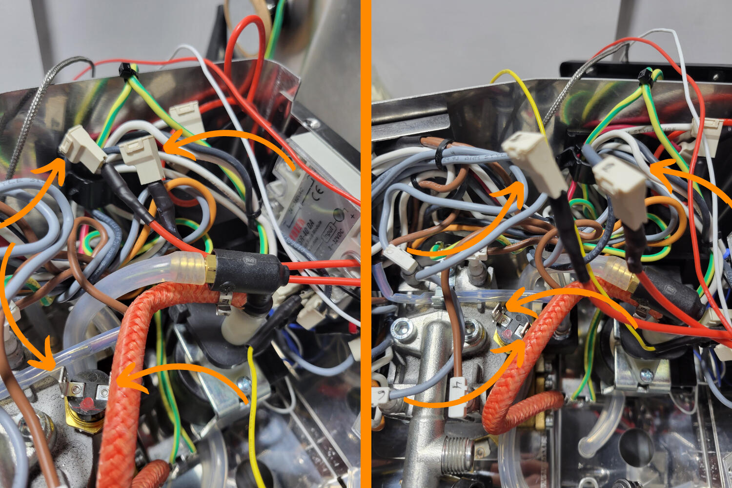
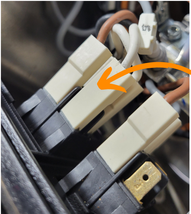
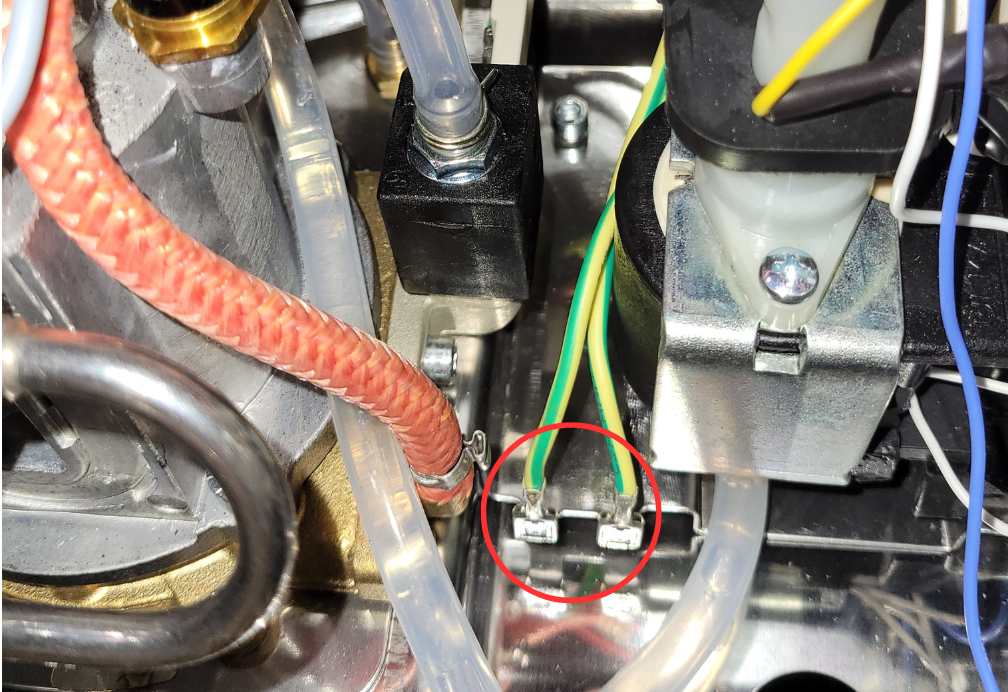
Two angles of the steam relay connectors attached to connectors #1 and #2. There are also arrows pointing to the no longer needed factory steam thermostat.
The picture above shows the two removed steam connector cables out of the way in the clip with the green/yellow cables. The #1 and #2 connectors are connected to the steam relay #1 and #2.
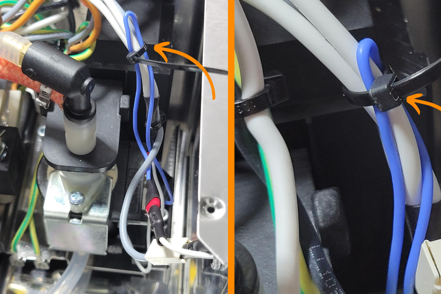
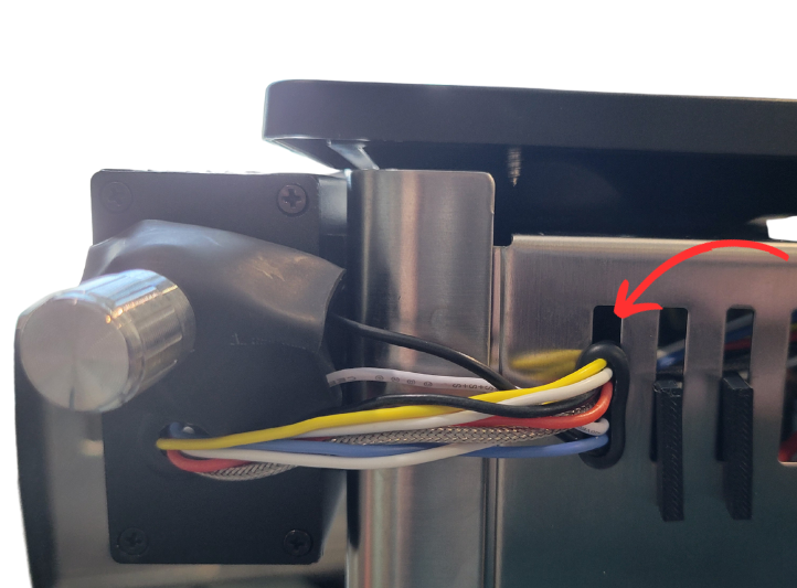
Feed New Wires Through Grommet
The final product. This is ideally how your wires will look. If you do not have the vent clip, you will likely need to use a different vent slot.
Take the ends of the blue and white wires from the Steam Relay and twist them together. Do the same for the red and white wires from the Brew Relay.
Push all wires through the same vent slot that you used for the flow control knob. Ideally, your grommet is not inserted into place in the vent yet. This will make pushing the wires through easier.
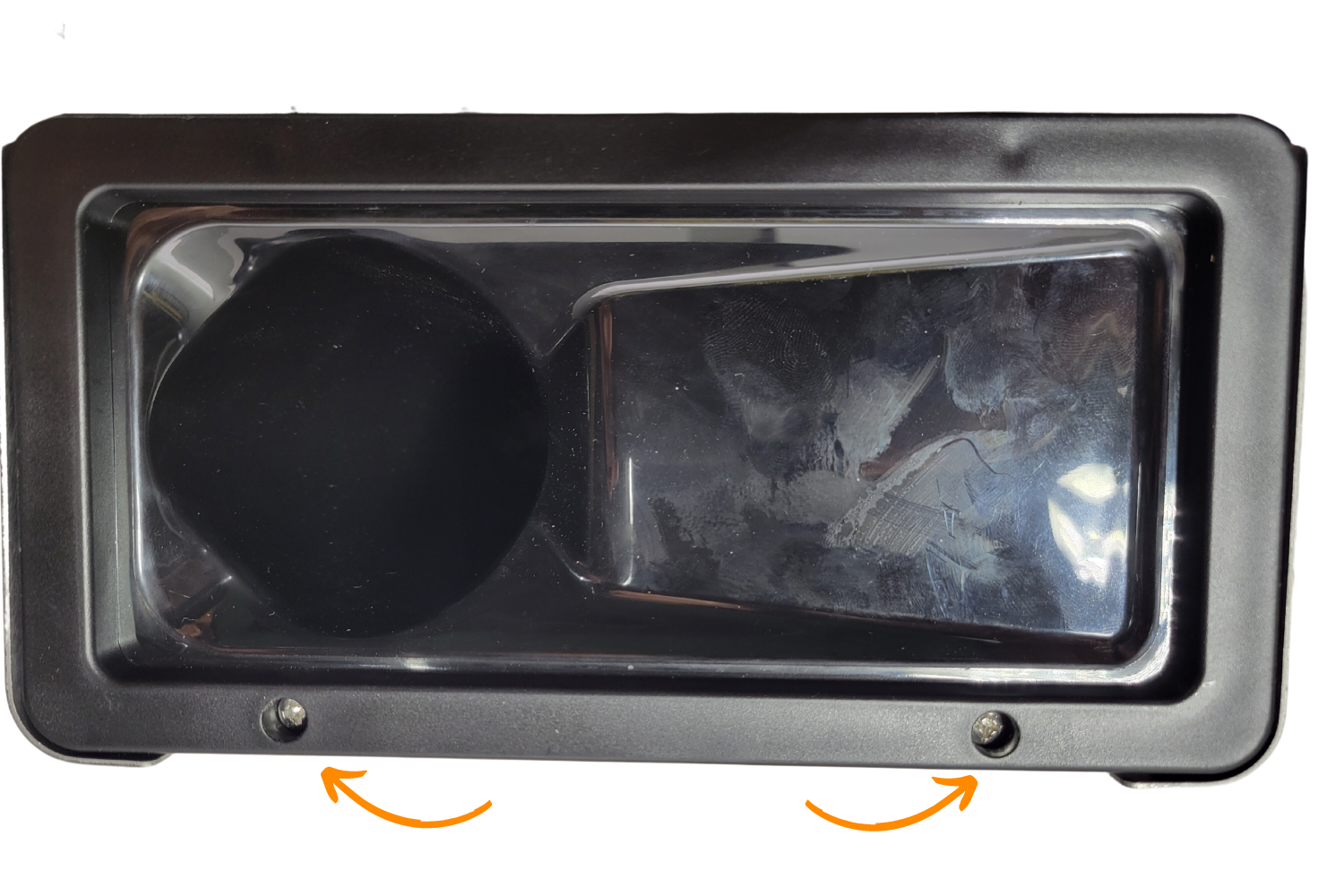
Next, take the PID + Enclosure and unscrew the 4 screws from the front plate.
Feed the wires from the relays and the ground (yellow ring connector) through the back grommet on the PID enclosure. The ring connector must be fed first or the rest will not fit. If the ring connector will not go through, remove the grommet from the PID housing, feed the ring connector through the grommet and the housing, then reinstall the grommet. .
Feed the wires a few inches (10cm) through the enclosure so that they can be reached from the other side..
Wires from the relays fed through the grommet in the machine and into the back of the PID housing through the grommet in the back.
Connecting Wires to the Controller
First, loosen all terminals on the back of the PID controller (except #3), enough that there is enough space for adding the cable ends.
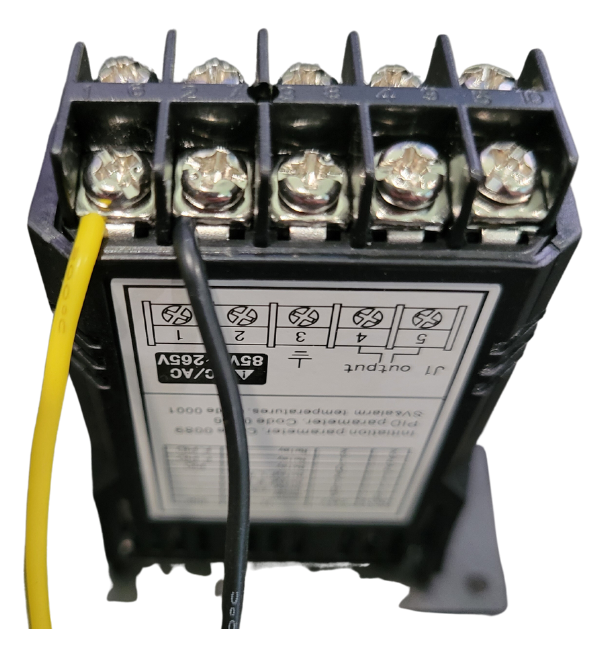
Next, take the black and yellow wires with bare cable ends (not the yellow ground wire with the ring connector). The black wire should go to the rocker switch neutral, and the yellow to the power cable hot.
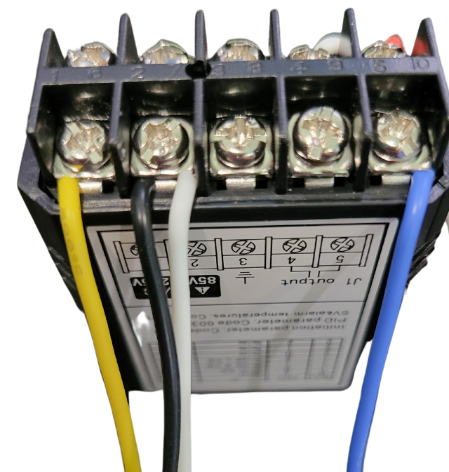
Take the yellow wire and connect it to PID Terminal #1.
Take the black wire and connect it to PID Terminal #2.
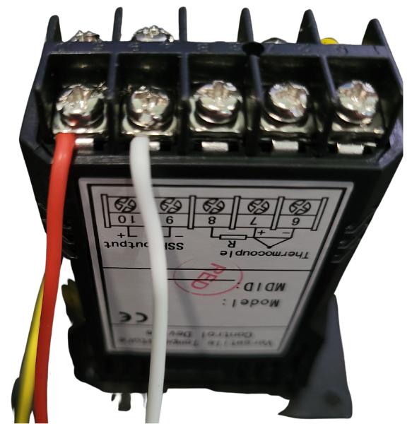
Next, take the twisted red and white wires with the bare cable ends, which go to the brew relay.
Take the white wire and connect it to PID Terminal #9 (SSR -).
Take the red wire and connect it to PID Terminal #10 (SSR +).
NOTE: This red wire connected to PID terminal #10 will have to be disconnected to configure your PID controller. To save time, you can leave it disconnected.
If you're not doing the steam upgrade, you won't have a blue and white wire to connect for this step.
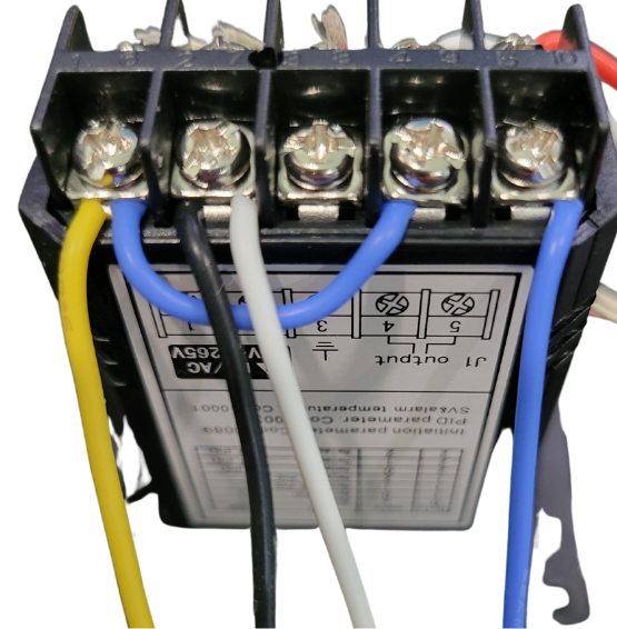
Next, take the twisted white and blue twisted with bare cable ends, coming from the Steam Relay.
Take the white wire and connect it to PID Terminal #2. There should now be two wires connected to PID Terminal #2, one black and one white.
Take the blue cable and connect it to PID Terminal #5.
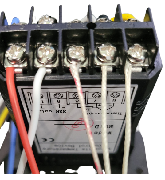
Next, take the 3 temperature sensor cables. Depending on your temperature sensor, you either have 2 red wires and 1 white wire or 2 white wiresand 1 red wire.
Whichever wire you only have one color of, take that wire and connect it to PID Terminal #8.
The other two wires that are the same color will be connected to PID Terminal #7 and Terminal #6.
Lastly, take the small blue jumper wire
Connect one end to PID Terminal #4 And the other end of the jumper wire to PID Terminal #1. There should now be 2 wires connected to PID Terminal #1, one yellow and one blue.
You should now be wired! Check your connections.

NOTE: The image above on the left hand side with terminals #1 to #5 is upside down.
The correct wiring for the PID controller:
1- yellow and blue jumper; 2- white and black, 4- blue jumper, 5- blue (not jumper), 6- white from thermal sensor, 7- other white from thermal sensor, 8- red/white from thermal sensor, 9- white, 10- red.
Here is a chart with information on each cable, its location, and its purpose.
| Connect Cable | Purpose | To PID |
|---|---|---|
| Yellow Wire Piggy Back | Power Cable (Hot) Tap | PID Terminal #1 |
| Small Jumper | Jumper Wire | PID Terminal #1 to #4 |
| Black Wire Piggy Back | On/Off Neutral Tap | PID Terminal #2 |
| Steam SSR #4 (White) | Steam Relay (-) | PID Terminal #2 |
| Empty | Empty | PID Terminal #3 |
| Steam SSR #3 (Blue) | Steam Relay (+) | PID Terminal #5 |
| Temp Sensor Double Color | Temp Control | PID Terminal #6 |
| Temp Sensor Double Color | Temp Control | PID Terminal #7 |
| Temp Sensor Single Color | Temp Control | PID Terminal #8 |
| Brew SSR #4 (White) | Brew Relay (-) | PID Terminal #9 |
| Brew SSR #3 (Red) | Brew Relay (+) | PID Terminal #10 |
Your PID controller is now wired!
Carefully review all wiring in previous steps!
Plug the machine back in and turn on the switch. The PID screen should turn on. As soon as the PID screen illuminates, turn the machine off.
Next, turn the machine off, unplug it from the back of the machine, and unplug the power cable from the power outlet.
Before the next step, ensure that you have disconnected PID terminal #10 (red wire).
If the controller turned on, move onto the next step. This will prevent the machine from heating up, making configuring the PID controller easier and less stressful.
Controller Powers on When Machine is Off
Disconnect the power cable from your machine and swap your on/off rocker power switch tap to the other top connector on the on/off rocker switch.
Controller Screen Reads EEEE
Your temperature sensor is not correctly installed or it was damaged it during installation.
Controller Doesn't Have Power
You missed a wire somewhere. Check your power cable entrance wiretap. Check your on/off rocker switch neutral tap. Check the connections on the back of your PID controller. Check to see if your relays illuminate when the machine is powered on.
I still can't figure it out
Send an email to sungazecoffee@gmail.com and we will help you figure it out.
Putting the machine back together.
Disconnect the red wire from PID terminal #10 and cover it with the included cable jacket. Make sure the bare cable end is not touching anything that could cause a short.
Make sure the machine is unplugged. Leave the PID enclosure and wires on the side of the Gaggia, hanging for now.
Move the boiler out of the way and put the steam knob trim piece back on.
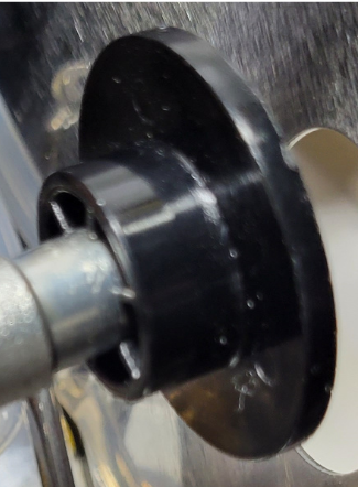
The correct way to fit on the steam knob trim piece.
Next, slide the steam knob back on from outside of the machine.
Put the boiler and grouphead assembly back in place, and then finger-tighten the four screws that went around the grouphead. Once they are snug, tighten them with an allen wrench.
How to fit the steam tube back together.
Feed the steam wand connector back into place and finger tighten the locking nut. Once it is snug, tighten it with pliers.
The final step is to put the top cover back on. First check that the Steam Relay and the wires coming from it are clear of the hole where the top will screw on. Reposition it if necessary.
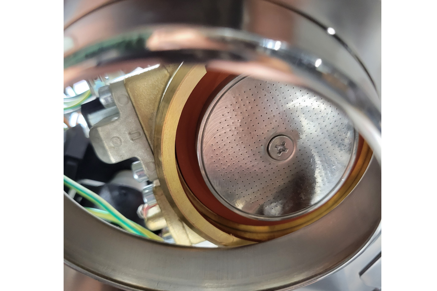
Next feed the front of the cover into the machine. When it is in place, looking down the funnel, bend it until you can line up the funnel with the funnel hole in the case. It may be snug as the funnel may butt against the relay.
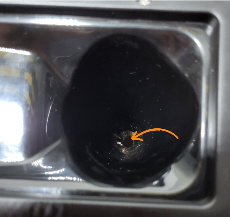
The image above shows the hole you should see when you properly line up the water funnel.
Apply pressure to the back and screw in the two top cover screws.
Configuring the PID Controller.
You may take the ring terminal of the yellow wire and screw it into one of the eight screw holes on your PID controller enclosure. This is only temporary for this step while we test the machine.
Plug the power cable into the back of the machine. Be sure that the wire from PID terminal #10 is disconnected and electrically isolated.
Flip the power switch, and the PID temperature controller screen should illuminate.
Because PID terminal #10 is disconnected, the boiler will not heat. Do not be alarmed if the temperature does not rise.
If you'd like to learn more about your PID controller, click the button below.
Press Set on the controller; ‘0000’ should start flashing.
You will need to enter into the ‘0089’ menu.
Press the > button to scroll the selected integer to the right, and use the ↑ or ↓ button to change the integer values either up or down. When ‘0089’ is displayed, press the Set button.
If you would like to set the controller to Farenheit, , use the ↑ or ↓ button to scroll until ‘CorF’ is displayed, then press the Set button.
In the ‘CorF’ menu, change the value from 0 to 1 using the ↑ button, then press the Set button. This will change the controller from Celcius to Fahrenheit.
Toggle the On/Off switch on your machine to reset the controller. Go back to the ‘0089’ menu.
Press the ↑ or ↓ key until ‘inty’ is displayed and press the Set button.
Using the ↑ or ↓ keys, change the ‘inty’ value to P10.0 and press the Set button.
From the ‘0089’ menu, navigate to ‘outy’ and press the Set button.
Change the ‘outy’ value to 2 and press the Set button.
From the ‘0089’ menu, navigate to ‘Psb’ and press the Set button.
Change the ‘Psb’ value to -14.4 for Farenheit and -8 for Celcius, then press the Set button.
From the ‘0089’ menu, next navigate to ‘rd’ and press the Set button.
Change the ‘rd’ value to 0 and press the Set button.
This is the last step in the ‘0089’ menu; navigate to ‘End’ and press the Set button.
Next, navigate to the ‘0036’ menu and press the Set button.
Navigate to ‘P’ and press the Set button.
Change the ‘P’ value to 4.5 and press the Set button.
From the ‘0036’ menu, now navigate to ‘I’ and press the Set button.
Change the I value to 64 and press the Set button.
From the ‘0036’ menu, now navigate to ‘D’ and press the Set button.
Change the ‘D’ value to 16 and press the Set button.
From the ‘0036’ menu, now navigate to ‘SouF’ and press the Set button.
Change the ‘SouF’ value to 0.2 and press the Set button.
This is the last setting in the ‘0036’ menu, navigate to ‘End’ and press the Set button.
Navigate to the ‘0001’ menu and press the Set button.
Navigate to ‘AH1’ and press the Set button.
Change the ‘AH1’ value to 278 for Fahrenheit and 136.6 for Celsius; press the Set button.
From the 0001 menu, now navigate to ‘AL1’ and press the Set button.
Change the AL1 value to 279 for Farenheit and 137.2 for Celcius; press the Set button.
From the ‘0001’ menu, navigate to ‘sv’ and press the Set button.
Change the ‘sv’ value to 200 for Fahrenheit and 93.2 for Celcius.
From the ‘0001’ menu, navigate to ’End’ and press the Set button.
Turn the machine off and disconnect the power cable.
Last Few Steps
Reconnect the red wire to PID Terminal #10.
looking at the PID controller head on, put a screw through the faceplate hole, then the yellow cable with a ring connector end. Now thread the screw through the post hole.
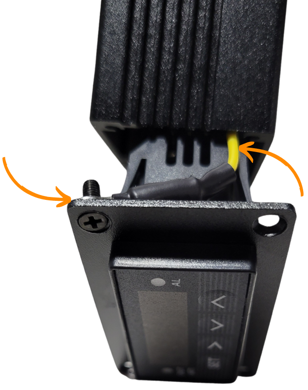
Use the screws to put the controller enclosure back together
Looking at the PID controller head on, mount it to its housing by screwing in the four faceplate screws. After the controller is back together, take any excess wire and push it back into the machine.
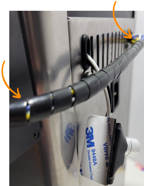
Use the spiral cable sleeve to wrap around your controller cables.
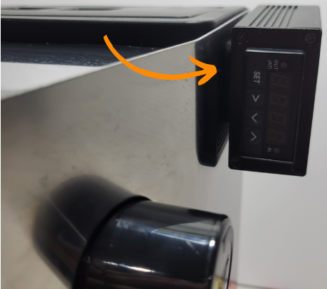
The next step is to mount the PID controller and pump switch.
These can be mounted anywhere on the machine you would like; in this example they are mounted to the back side of the right hand corner.
Use the alcohol wipes from the kit to wipe the area where the controller will be mounted as well as the side of the PID controller housing.
Use the large adhesive pad and adhere it to the PID enclosure. Attach the PID to the desired location.
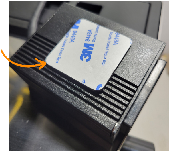
Attach the PID controller enclosure to the machine.
Clean the location for the pump dimmer switch and the back of the switch. Use the small adhesive tape to mount it to the desired location. Here, it is mounted on the back of the PID housing.
Attach the pump dimmer switch to the enclosure.
Installation with vent clip

Installation without vent clip
Plug the machine back in.
Leave the machine running for about 15 minutes. Ensure that the temperature stays stable and doesn't vary too much from the setpoint.
After 15 minutes, hold the > button on the PID controller for about 5 seconds. The Out (AT) light on the front of the controller will start to blink.
The machine will now run an autotune for the P, I, and D parameters to find what works best for your machine.
If the brew button doesn't seem to be working, the pump dimmer switch may be set too low.
Verify your brew and steam functions are working, then click the button below.
Congratulations on the install!
Here's how you should handle pre-infusion
Please email me any questions at sungazecoffee@gmail.com
If you purchased this kit, please consider leaving me a review on Amazon, it helps me more than you know.
Making this guide and these kits was significantly harder and more stressful than I would have thought. I appreciate any and all feedback and I hope you enjoy your fully modified machine!
If you didn't purchase my kit but used my guide, consider donating below.
Where to Buy
Click any button below to purchase a premade Gaggia upgrade kit.
Rotary flow control for pre-infusion & PID control for brewing & steaming. Also comes with two portafilter discs, a wdt tool, a portafilter keychain, and a backup brew and steam relay.
Rotary flow control for pre-infusion & PID control for brewing & steaming.
Rotary flow control for pre-infusion & PID control for brewing. Stock steaming capability.
Rotary flow control for pre-infusion.
Save headache and time with an already built and modified Gaggia Classic Evo Pro.
Clicking the button above will result in affiliate commissions on Amazon, helping support our work!
Our Reccomended Gaggia Upgrades & Accessories
Purchase any of the recommended accessories below and we will receive affiliate commissions. An easy way for you to support our work!
Gaggia Maintenance
Anything you might need to maintain your Gaggia Classic, Gaggia Classic Pro, or Gaggia Classic Evo Pro.
Other Gaggia Mods
Other easy mods you can install in your Gaggia Classic Pro & Gaggia Classic Evo Pro
Puck Prep
Upgrades to help make your puck prep more consistent.
Workflow Upgrades
Upgrades to make your espresso workflow feel professional.
Grinders
High quality options for both manual and electric grinders.
Machines
Links to various colors of the Gaggia Classic Evo Pro.
Coffee Roasting
An easy way to get into the art of coffee roasting. One of my favorite parts of my espresso setup.
Show Your Love for Espresso
Purchase any of these to help feed your love for the art of espresso.
Parts Identification
Here are links to the parts you need to purchase for your install.
Main Components
Tools
Cable Bundle
Misc Parts
Purchasing the components above will result in an affiliate commission to help support our work
2 -> 3 Prong Ground Upgrade
The Gaggia has 5 areas that can be grounded to ensure redundancy and safety.
Here is how we're going to wire this up.
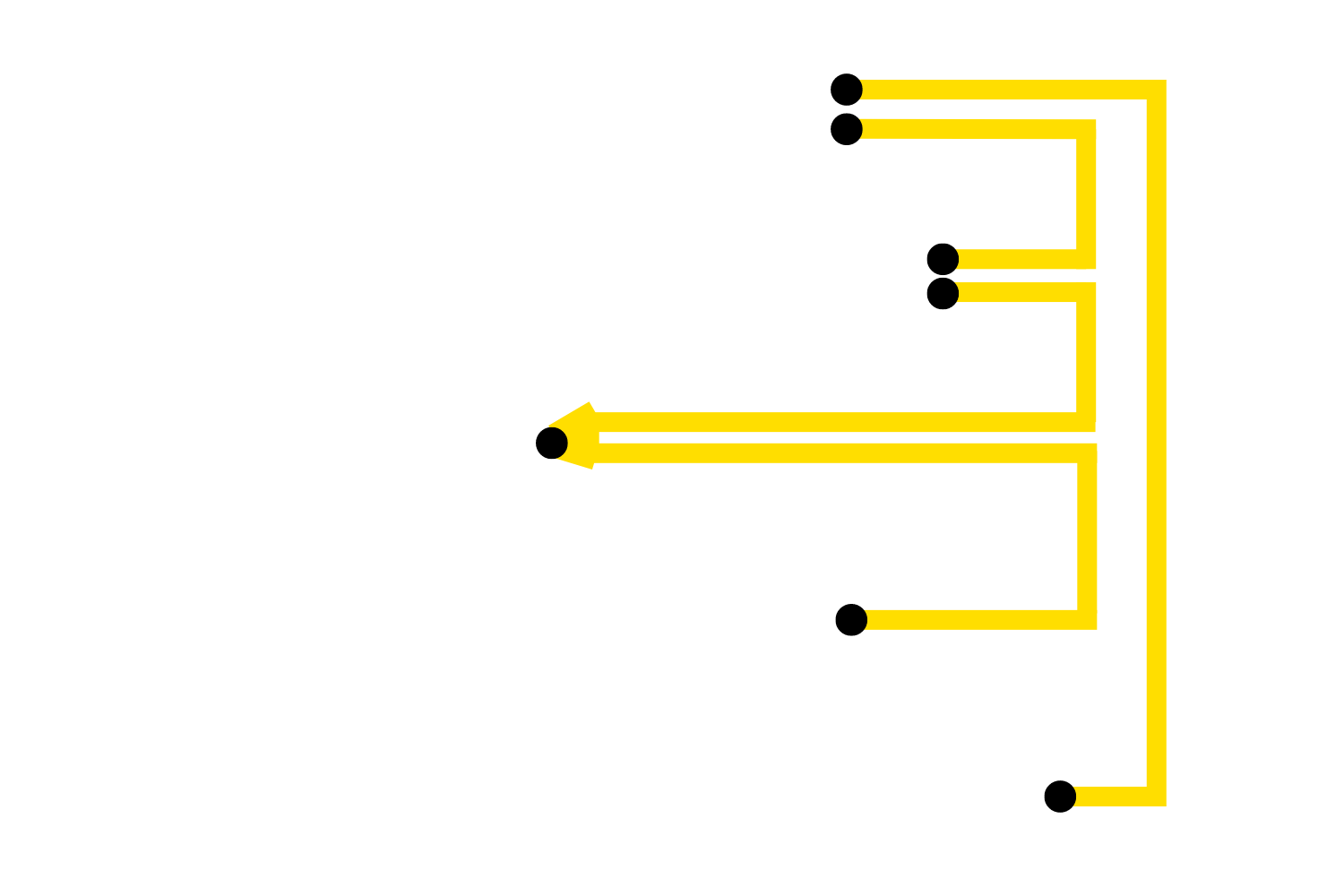
The top cover will connect to the pump pount and the power cable entrance.
The pump wil connect to the top cover and the solenoid (frankenstein cable)
The solenoid will have a single cable connected to it that connects to both the pump and the top of the boiler.
The top of the boiler will be connect to the solenoid
The power cable entrance ground we're adding will be connected to the top cover.
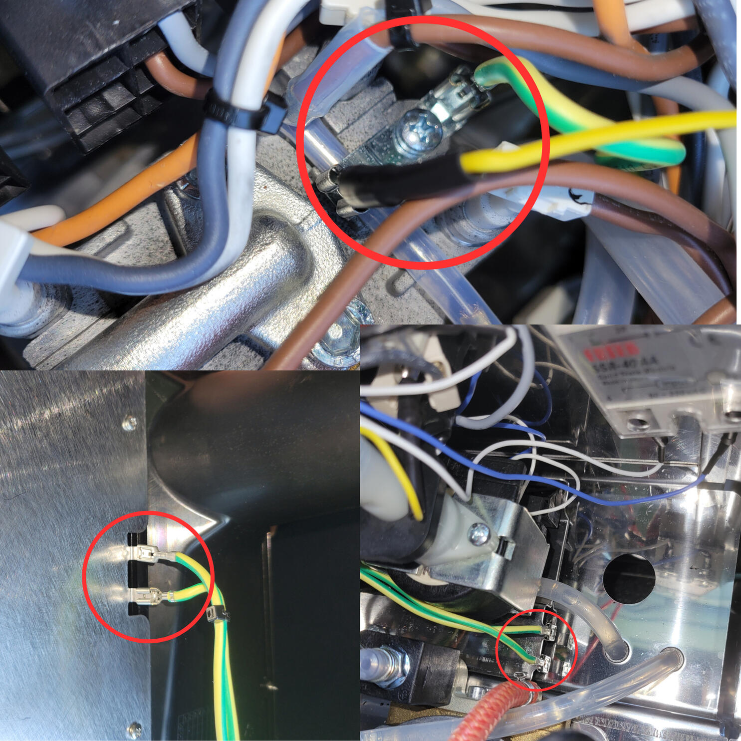
The top image shows the location ontop of the boiler where the two grounding posts are located.
The bottom left image shows where the two grounding tabs are on the metal top cover. .
The bottom right image shows where the two grounding tabs are on the brew pump mounting plate.
The image below shows multiple angles of the solenoid. The image on the left has two circles, one around both grounding post for the pump with both connectors and one on the solenoid with two cables merging into one, indicated by the double arrow.
If you look to the right, you'll see the frankenstein cable plugged into the solenoid below the set of double wires.
To get started, take out the 4 yellow wires with female ends from your ground upgrade kit.
Grab your yellow wire with two female ends that converge into a single female end.
Take the single end of the wires and connect it to the free location on the soleniod.
The image below has an arrow pointing to where you need to connect the frankenstein ground wire to your solenoid.
Take one of the two free ends and connect it to one of the unused grounding posts on the metal pump mounting plate.
Lastly, we need to take the last free end and connect it to the unused grounding location on the top of the boiler.
We're now going to connect one of the single yellow wires from one of the two free slots on the top cover.
Now, take the other end and connect it to the last free grounding post on the metal pump mounting plate.
Lastly, take your final yellow wire and connect it to the last free grounding location on the metal top cover.

We're now going to connect the other end to the single post side of the new power cable entrance.
We're now going to connect the other end to the single post side of the new power cable entrance.
Make sure to attach the ground wire to the single side of the power cable entrance fitting. You need to make sure you are connected to the ground prong side.
The image on the left has an arrow pointing to the side where the ground wire should attach. The image on the right has arrows pointing to the ground connector and the yellow ground wire.
You can now put your power cable entrance back in place and put your machine back together.
You have officially grounded your machine!
Thank you for your purchase of a newly modified Gaggia Classic Evo Pro!
There are two extra bags included in a modified machine. One for accessories and another for tools and extras.
The accessories bag is meant to be opened, and includes a wooden WDT tool, portafilter puck screens, a portafilter keychain, and a Uniball pen.
The extras bag includes the parts needed to open your machine up if needed. There is a screwdriver, 17mm wrench, etc. This bag ideally shouldn’t ever be needed but is incredibly convenient to have in the unlikely event of part failure.
If you have any questions, email us at Sungazecoffee@gmail.com or call/text Chris at 815-618-9355 for further assistance.
Just so you know… your order helped support a small business in Woosung, Illinois! Your order is appreciated more than you know 😊 Seriously, thank you!
HOW TO USE YOUR NEWLY MODIFIED GAGGIA CLASSIC PRO
Step 1.) Setup
• Clean the group head and portafilter thoroughly.
• Fill the water reservoir with fresh water.
Step 2.) Prime the Pump
• Turn on your machine by flipping the power switch (far left button with a O and -)
• When powering on a new machine or after extended non-use, prime the pump.
• To do this, fill the water reservoir, turn on the machine, and flip the brew switch until water evenly flows from the portafilter head.
• This ensures the pump is filled, vital for effective brewing and water circulation within the boiler.
• Note: If your machine seems to not be pumping water, your brew knob may be turned off. To check, turn you flow control knob on the back of your black PID enclosure in either direction until you hear a click. The click means the water flow is off. Once you feel the click, turn it all the way in the opposite direction to fully open it.
Step 3.) Preheat
• Wait for about 20 minutes for proper preheating; leaving the portafilter inserted helps it heat alongside the boiler.
Step 4.) Grind Coffee
• Grind fresh coffee beans to a fine consistency using a burr grinder, adjusting depending on how your shots are pulling. Freshly roasted beans are incredibly important.
Step 5.) Portafilter Preparation
• Remove the portafilter, wipe off any debris, and ensure it's dry to prevent water taking the easiest route during brewing.
Step 6.) Dose and Tamp
• Measure coffee grounds for consistency, adjusting for bean type and grind size. The Gaggia stock portafilter takes about 14-16 grams or 12-14 grams if using the included portafilter puck screen.
• Distribute grounds evenly, tamp down snugly, but not too tightly.
Step 7.) Flush Water
• About a minute before brewing, run water through the group head to ensure a natural flow of water.
Step 8.) Insert Loaded Portafilter
• Lock the portafilter into the group head, ensuring a snug fit.
Step 9.) Brewing with Pre-Infusion
• To pull your shot, you will flip the brew switch (middle button)
• With the dimmer knob fully open, start brewing until the first signs of espresso.
• Turn off the dimmer knob off quickly, you want to hear the click.
• After 5-10 seconds of pre-infusion, gradually turn it back to 100%, adjusting flow variably for a balanced extraction.
• After you have between 1-1.75 ounces of espresso, flip your brew switch off.
Step 10.) Clean Shower Screen
• After brewing, remove your portafilter.
• Briefly flip the brew switch to clean the shower screen and wipe it with a towel if possible.
Step 11.) Steaming
• If your machine is modified, it's already set to the ideal steaming temperature.
• To start the steaming process, you will need to flip your steam switch (right hand switch with a cloud). You will want to start frothing your drink somewhere between 235-260 degrees Fahrenheit.
• Before you steam your drink, purge the steam wand into an empty cup by opening the steam valve on the right hand side of the machine.
• Now you can froth your drink, as soon as you are done frothing, close your steam valve and flip your steam switch off.
• Note: It is important to not leave your machine unattended while the steam switch is flipped. You must open the steam valve before the temperature reaches 275 degrees or you may blow your thermal fuse. The thermal fuse and easily be replaced but is a major annoyance.
Step 12.) Clean Up
• Knock out the coffee puck, rinse the portafilter, and clean the drip tray and water reservoir regularly.
Step 13.) Enjoy Espresso!
• Your espresso is ready to be enjoyed!
If you have any questions, email us at Sungazecoffee@gmail.com or call/text Chris at 815-618-9355 for further assistance.
Relay Installation Menu
Your kit either come with two individual relays or two relays connected together on a black vent clip. Based on the images below, click the button for your kit.
Individual relays
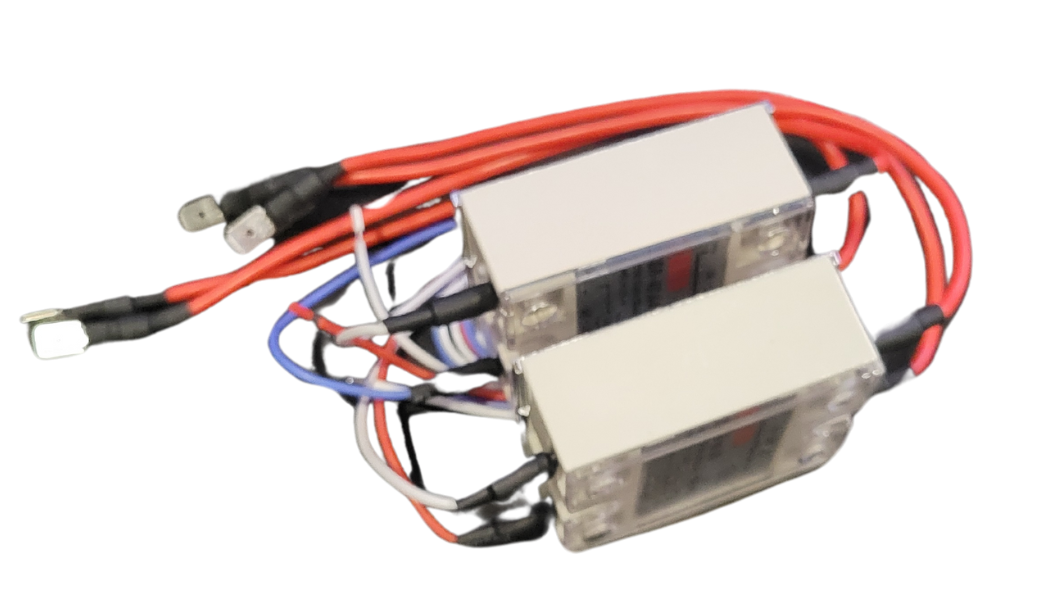
Relays connected to the vent clip
Click the button below for your configuration.
Vent Clip Relay Install
The final installation. Notice that the steam relay is mounted on the right and the brew on the left. The vent clips will be inserted into the second and thirft farthest to the right vent hole.
Open up your thermal paste tube and apply the rest of the compound to your relays like the image below.
Insert your relays with vent clip into the second and third farthest right vent hole.
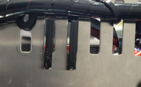
When your relays are properly inserted, they should sit like they do in the image below.
That's it! Your relays will now sit down and out of the way.
If you have a model or install that inhibits your ability to do this, please choose the other installation method for your relay below.
Understanding Your PID Controller
Press the SET button to enter the setting mode.
Use the >, v, and/or ^ buttons to navigate through the parameters.
Press the SET button again to confirm your selection.
0089 MENU – INITIAL FUNCTION PARAMETERS
Inty stands for Input Type- the type of sensor being used to measure temperature. The supplied sensor is a RTD PT100, and the corresponding code is PT10.0. This setting is used to select the type of input sensor that is used to measure the temperature of the boiler
Outy stands for Control Output Type. There are many ways to use a PID temperature controller, but this configuration is a solid-state relay (SSR) with a relay alarm, which has code 2. This setting is used to select the type of output that is used to control the temperature of the boiler.
Hy stands for Hysteresis. This is used for the autotuning Pv bias. The ideal setting for this parameter is 0.003. This setting is used to adjust the autotuning algorithm to account for any bias in the process variable (PV) measurement. This value is used when the controller is not using its PID capabilities.
PSb stands for Pv Bias, or Offset Temperature. This setting accounts for the drop in temperature between the boiler and the grouphead (as the grouphead is not directly heated). The ideal setting for this parameter is -14.4°F (-9.7°C). The PID will now display the estimated temperature at the grouphead, not the boiler itself.
Rd stands for Control Action Type. PID temperature controllers can be used for heating systems and cooling systems. Since this system heats when powered, the value is 0. This setting is used to select the type of control action that is used to regulate the temperature of the boiler.
Corf stands for Temperature Selector. The ideal setting for this parameter is 1 for Fahrenheit (0 for Celsius). This setting is used to select the temperature scale that is used to display the temperature of the boiler.
0036 MENU – PID PARAMETERS
P stands for Proportional Band, which considers the difference between setpoint value and current temperature (called error). The ideal setting for this parameter is 4.5. This setting is used to adjust the sensitivity of the controller to changes in the process variable (PV). A higher value of P will result in a more sensitive controller. P
I stands for Integral Timer, which looks at cumulative error over time. The purpose of this value is to prevent asymptotic approach to set temperature. The ideal setting for this parameter is 64. This setting is used to adjust the rate at which the controller responds to changes in the PV. A higher value of I will result in a slower response time.
D stands for Derivative Timer, which looks at the slope of the error versus time. This parameter dampens the overshoot and undershoot oscillations, honing in on a stable output. The ideal setting for this parameter is 16. This setting is used to adjust the rate at which the controller anticipates changes in the PV. A higher value of D will result in a more anticipatory controller.
0001 MENU – SET VALUE AND ALARM PARAMETERS
Brew Temperature Setting
Sv stands for Set Value, the ideal temperature for the boiler (or if using an offset, grouphead). A typical setting for this parameter is 200°F (93.3°C). You may want to adjust this value up or down based on the bean, which can be done simply by pressing the arrows on your PID Controller.
Steam Temperature Settings
AH1 stands for Relay J1 Pull-In Set Value. The ideal setting for this parameter is 278°F (136.6°C). AH1 stands for Relay J1 Pull-In Set Value, which in this configuration is the steam temperature. The AH1 value should always be less than AL1.
AL1 stands for Relay J1 Release Set Value. The ideal setting for this parameter is 279°F (137.2°C). AL1 stands for Relay J1 Release Set Value. This setting is used to set the temperature at which the relay J1 releases. The AL1 value should always be more than AH1.
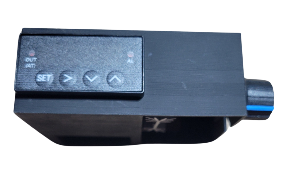
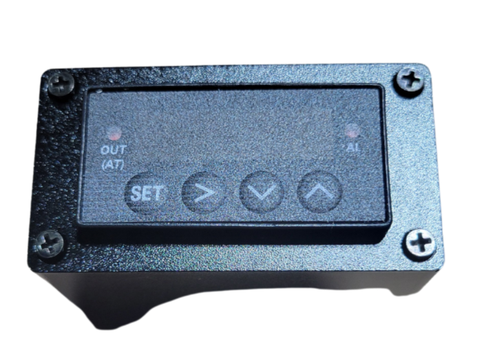
Choose Your Controller Enclosure
For your PID controller, you either have a 3D printed enclosure or aluminum enclosure. Based on the pictures below, click on your installation guide. If you have not purchased a PID kit from Sungaze Coffee, you should select aluminum enclosure.
This is for the 3D Printed Enclosure with Flow Control Knob Only!
Click your model below to continue.
Came here on accident? If you have the aluminum enclosure, click here to go back
TROUBLESHOOTING & FAQ
Controller Powers Up When Machine is Off
If your controller powers up when you plug in the power cord (even with the Gaggia power switch off), you likely tapped the wrong cable on your power rocker switch. Swap the white wire on your power rocker switch from bottom to top and try again. Refer to the answer below for correct tapping instructions.
Power Cable Entrance Tap
Trace the wires from the power entrance of the machine. For a three-wire system, the ground wire (green) can be left alone. Tap the wire that makes a right turn and goes to the boiler area. Avoid tapping the wire leading to the front panel power switch.
Controller Screen Displays EEEE
Your temperature sensor is not correctly installed, wired, or it was damaged during installation. Make sure your temp sensor is firmly snug into the boiler of the Gaggia. Don't under or overtighten. If this is good, check your PID controller terminals 6, 7, 8. Ensure none of the wires are shorting or touching anything else
Machine Not Heating Up
Check if the LED on the SSR DA (solid-state relay) is coming on. If not, the input wires might be connected incorrectly (they’re polarity-sensitive). Swap them around if needed.
Steam Temperature Cycling
It’s normal for the steam temperature to fluctuate. The temperature for steaming control behaves more like a thermostat, swinging by about +/-30°F.
Sudden Steam Temperature Issue
The SSR AA (solid-state relay) used for steam control may have a shorter lifespan than the DA SSR. Reach out to Sungaze.
Wiring Colors for Thermostat and SSR
Gaggia frequently changes cable colors. To connect the thermostat to the SSR output, identify the cable connecting the brew thermostat and steam thermostat. The other two cables (one from each thermostat) should connect to the SSR output.
If you're still having issues, reach out to chris @ sungazecoffee@gmail.com or text/call 815-618-9355